setting up a router for an IT family
Hello reader!
We recently finished renovations and moved into a brand new apartment, so it’s time to install home Internet and local network. In most cases, for a home network it is enough to use one small router, preferably located in the geometric center of the apartment. In some cases, a switch or wifi repeater is added to expand the local computer network. However, we are a family of IT specialists and have certain wishes for the network:
connecting two desktop PCs,
separate interface for debugging network devices,
stable connection of the media zone (TV, a couple of set-top boxes),
a couple of stations with “Alice”,
super-micro-server (where not only supermicro),
transparent connection to remote development servers.
Based on the described wishes (as well as availability), I plan to use mikrotik (rb2011) as a central node. I learned a lot about setting up these routers from my network stack mentor at the university (hi, Alexey!) and thematic resources and conferences.
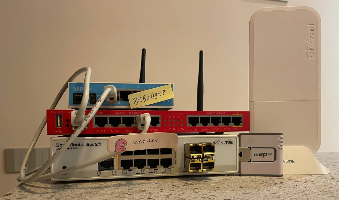
This article describes the basic setup of a router for use at home. In the future, I plan to describe additional settings based on the configuration described in this article and, to the extent possible, I will show some interesting cases and how they can be solved. You can use this configuration both in your home network and as a support solution in a small enterprise, or brush up on working with devices from this manufacturer.
There will be links to additional materials throughout the text, I recommend that you read them in order to understand some points about the settings and avoid mistakes when working with devices in the future.
Planning
First of all, it is necessary to decide on the computer network architecture to be implemented. Based on my wishes, I threw in the following picture:
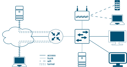
Since I’m doing it for an apartment, I’m planning the following networks:
management – here will be all device management interfaces (switches, routers, ipmi);
custom – I will connect TVs, computers, wifi devices;
servers – a network for developing and configuring various solutions;
providers – for multiwan implementation.
To begin with, we will implement simple user access to the Internet. The graphical diagram looks something like this:

The provider provides the Internet in an access, then the router directs user traffic and allows them to interact within the network.
So let's get started setting up!
Preparing the Router
This section contains a description of the minimum recommended steps to prepare the device for operation. It is recommended that such preparation be carried out with each new device.
Initial configuration option from the vendor can be find in confluence.
Download winbox. For me, it is much better than the web interface, and some commands are faster to find than in the terminal. Despite this, most configuration steps will be in the console to reduce the number of screenshots. After downloading the program, you need to connect to the device. Mostly, when connecting via cable, DHCP will issue an address and assign the router to 192.168.88.1. Feel free to reset all current settings, including passwords:
system/reset-configuration no-defaults=yes skip-backup=yes“
At my previous place of work, I had one case in version about 6.46 that after reconfiguring the router without a full reset, one of the interfaces remained in access on another vlan, although the port should have gone to trunk. Rebooting did not help, only resetting and re-rolling the same configuration file saved the situation.
If the configuration is useful in the future, you can save it to an internal flash drive and download (or send to the server) the current version with the following command: export file=backup.rsc
Lifehack
If someone configured the hardware before and did not provide the password (or you forgot it), then you can always clear the password (and the config along with it) using the button. To do this, turn off the power, hold the special Reset button, apply power and wait until the LED (usually marked ACT) stops blinking. Next, when connecting via a patch cord, put any static IP address on the PC interface and winbox will immediately see the device in its “neighbors”.
For all devices, it is recommended to update to the latest current version before starting work. Most likely, the update already fixed some bugs and vulnerabilities, so you won’t encounter them.
Review the version of the architecture on which you are configuring. This can be done either with the command/system resource print,
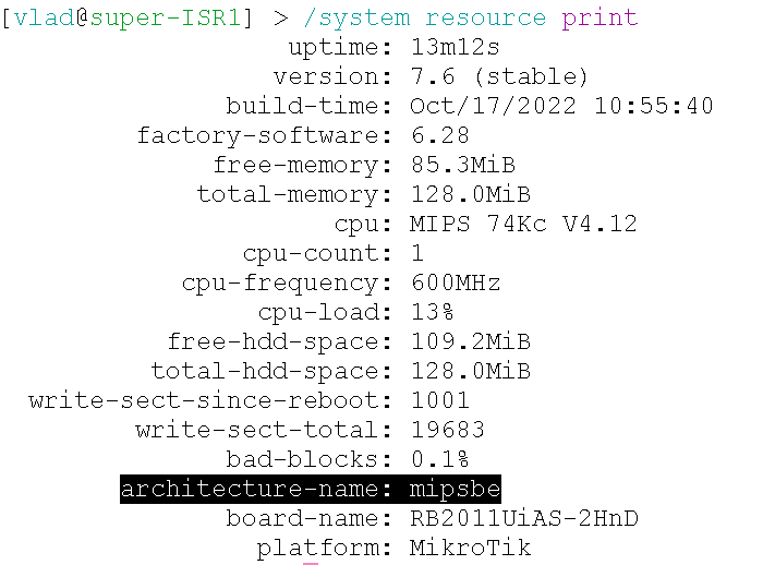
or by looking in winbox at the top of the window:

Let's go back to the official website Latvian vendor and download the stable version of RouterOS for the desired architecture. We add the downloaded file to the device’s flash memory and reboot it with the command system/reboot
Next, we will update the routerboard to the appropriate version. Go to the System section, select RouterBOARD and then click “Upgrade” or the same can be done with the command in the console:
/system/routerboard/upgrade
/system/reboot
We immediately disable interfaces that we are guaranteed not to use:
/ip service
set telnet disabled=yes
set ftp disabled=yes
set www disabled=yes
set api disabled=yes
set api-ssl disabled=yes
Let’s configure the device right away so that when bypassing LLDP, we immediately receive the correct name:/system/identity/set name="super-ISR1"
The last thing you need to do is create an account and disable the administrator:
/user/add name=vlad group=full comment="it's me!"
/user/disable admin
Great, your device is now updated and ready to be configured.
Interface settings
The current section describes how to create and configure interfaces and connect logical and physical entities.
VLAN allows you to segment networks quite flexibly and conveniently. In this case, all vlans are terminated on the router side. In the future I plan to add a switch and implement a router-on-a-stick (router on a stick), giving these vlan's in the trunk. First, let's create bridges on which our vlans will hang:
/interface/bridge/add name="br-lan" protocol-mode=none vlan-filtering=yes
/interface/bridge/add name="br-wan" protocol-mode=none vlan-filtering=yes
We will create 4 interfaces on the created bridges using the following commands:
/interface vlan
add name=v-10-usr vlan-id=10 interface=br-lan
add name=v-40-srv vlan-id=40 interface=br-lan disabled=yes
add name=v-50-adm vlan-id=50 interface=br-lan
add name=v-100-rtcom vlan-id=100 interface=br-wan
The interface specifies the corresponding bridge to which the vlan is bound.
Additionally, we will configure the remaining interfaces of the router. When assigning interfaces, I was taught the following rule: uplinks (and some equipment) at the end of the range, users at the beginning. It is worth considering that rb2011 has gigabit ports 1-5, and 100MB 6-10. I assign the provider to SFP (in the future I will replace it with GPON according to the instructions https://habr.com/ru/companies/ruvds/articles/547442/ from oldadmin), and gigabit interfaces 1-3 for two PCs and a TV. The setup will look like this:
 /interface/
comment sfp1 comment="ISP R-com"
comment ether1 comment="User's lan"
comment ether4 comment="NOT USED"
disable ether4
disable ether5
disable ether7
disable ether8
disable ether9
disable ether10
We turn off the remaining interfaces either through the console, or by selecting the interfaces and clicking “Disable”. Be careful and do not turn off the port you connected to for configuration (in my case, ether6).
A good practice is to add interfaces to special lists, which can then be conveniently used in some places in the configuration, without listing each interface. First we create the lists:
/interface list
add name=WAN
add name=LAN
And then we add all the used interfaces to the corresponding lists:
/interface list member
add list=WAN interface=sfp1
add list=LAN interface=ether1
add list=LAN interface=ether2
add list=LAN interface=ether3
Now let's connect physical interfaces and vlan's:
/interface bridge port
add bridge=br-lan interface=ether1 pvid=10
add bridge=br-lan interface=ether2 pvid=10
add bridge=br-lan interface=ether3 pvid=10
add bridge=br-wan interface=sfp1 pvid=100
add bridge=br-lan interface=wlan1 frame-types=admit-only-vlan-tagged

/interface bridge vlan
add bridge=br-lan vlan-ids=10 tagged=br-lan,wlan1 untagged=ether1,ether2,ether3
add bridge=br-wan vlan-ids=100 tagged=br-wan untagged=sfp1
Access point
Additionally, we will set up temporary WiFi to release mobile devices onto the network. If only LAN is enough, then this section can be skipped.
Optimal WiFi setup in video.
Using the console, we will create a security profile – this is an entity that stores secrets and security settings for user connections:
/interface/wireless/security-profiles add name=wlan1-usr-sec mode=dynamic-keys authentication-types=wpa2-psk wpa2-pre-shared-key="xxxxxxxxx"
Now go to the Wireless section. Double-click on the existing interface. We immediately set the mode Advanced Modeto see all settings. We configure the parameters according to the picture:
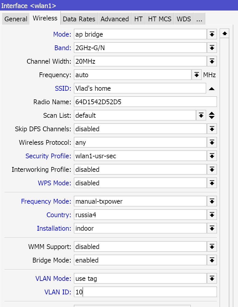
Since rb2011 only has a 2.4 GHz radio module, we configure it. Disable B range (not sure if it is still in use), indicate your own network name and the security protocol created earlier. Next, we indicate the russia4 region, installation in the apartment and manual power adjustment. In the Tx Power tab, select all rates fixed and the value 9-10 dBm. Since the antenna gain is about 4 dBi, the total output power is about 12-13 dBm, which in terms of mW is about 15-20 mW.

This completes the setup. If you click the “Enable” button, you can connect to the created access point.
Addresses
This section is devoted to setting up IP interfaces and is the final point for work.
Let's set up the device's connection to the Internet, which differs from provider to provider. In my case, the router receives parameters via DHCP, so it’s enough to connect the client to the interface with the following command:
/ip/dhcp-client/add interface=v-100-rtcom
To verify that the address has been received, you can run: /ip/dhcp-client/print
In the future I plan to purchase GPON and set up a connection with the provider through it via existing instructions by @oldadmin
Now let’s assign IP addresses to the previously created vlans. To do this, go to the ip section and, in accordance with the vlan numbers, distribute addresses to the networks:
/ip/address
add address=10.0.10.30/27 interface=v-10-usr
add address=10.0.50.254/24 interface=v-50-adm
add address=10.0.40.254/24 interface=v-40-srv disabled=yes
The next important step is setting up a dhcp server. It's easier to use the wizard inside winbox than to configure all the fields manually. To do this, in the section IP>DHCP Server choose DHCP Setup.

We click next several times until we reach DNS. Here we immediately indicate the required DNS. You can correct it later in IP>DHCP Server, tab Network.
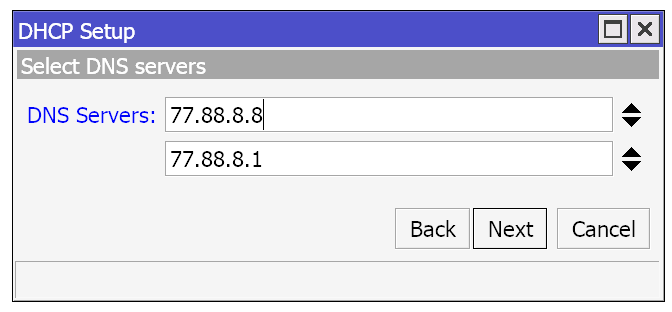
The next stage where you can stop is Leases time. By default, 10 minutes are offered, but it is better to increase the rental time to 2-3 hours.
Great, now all clients receive IP addresses and can communicate with each other. Let's start setting up user access to the Internet.
User NATing
More details about setting up NAT
Despite the fact that the router itself is already looking at the Internet, if you “knock” on the Internet from your computer now, nothing will work. For testing, you can issue a request from the user network interface:
/ping 8.8.8.8 src-address=10.0.10.30
For setup and further convenient configuration, let’s create lists of IP addresses:
/ip firewall address-list
add address=10.0.10.0/27 list=lan-10-usr
add address=10.0.40.0/24 list=lan-40-srv
add address=10.0.50.0/24 list=lan-50-adm
add address=10.0.10.0/27 list=inet-access
By adding networks to the inet-access list, we will allow connected devices to access the Internet. Now let's configure user masking. There are two options for this:
If the provider statically gives one address, then it is better to use the src-nat setting
/ip/firewall/nat> add chain=srcnat src-address-list=inet-access action=src-nat to-addresses=[IP адресс от DHCP клиента]
In this case, processing will be faster, since the device will not have to look for an address to which to forward the packet ().
If after each reboot the provider gives a new address, then you will have to use masquerade:
add chain=srcnat src-address-list=inet-access action=masquerade
Now, when checking, the packages will be sent and Internet pages will be loaded, hurray!
Conclusion
The basic setup can be considered complete. The created network is already being actively used and is being developed as far as possible.
The minimum functionality described in the article allows you to connect clients to the network like a regular home router. In the future I will implement and describe:
Setting up a poe switch and access point;
Creating tunnels to access your servers and home network;
As well as other small notes (for example, home web page, hotspot, simple multiwan), which can be helpful when setting up a network in a small organization.
I also recommend viewing several materials that can help you customize the configuration, increasing the reliability and security of your device:

