Principle of ranging between UWB transceivers (State machine for DS TWR)
There are radio transceivers that can measure the exact time of sending and receiving binary radio packets. The word exactly means that with 15ps sampling. An example is the ASIC DW1000. This is a very useful feature as it opens the way for measuring the distance between transceivers.
You can read about the DW1000 chip here https://habr.com/en/articles/715936/
However, the DW1000 chip itself cannot calculate TOF at the hardware level, which appears in the formula for calculating the distance between transceivers.
Calculating TOF is purely software work that must be done at the Firmware level.
There was already a text about the principle of measuring the range between two radio transceivers here https://habr.com/en/post/719542/
But that SS-TWR method gives low measurement accuracy, since it does not take into account the instability of quartz resonators. To compensate for the instability of the quartz resonator on two copies of UWB transceivers, DS-TWR technology is used.
About the derivation of the formula for calculating the range, taking into account the compensation for the instability of the frequency of quartz resonators, there is this text https://habr.com/en/post/723594/

Here is a timing diagram for one DS-TWR ranging session.

A DS-TWR session consists of two symmetrical SS-TWR phases (phase1, phase2). Each phase is essentially an ordinary SS TWR.
How to implement the DS-TWR protocol in code? Here, of course, the automaton methodology of software development simply suggests itself.
This is how the state machine for managing the ranging session looks like.
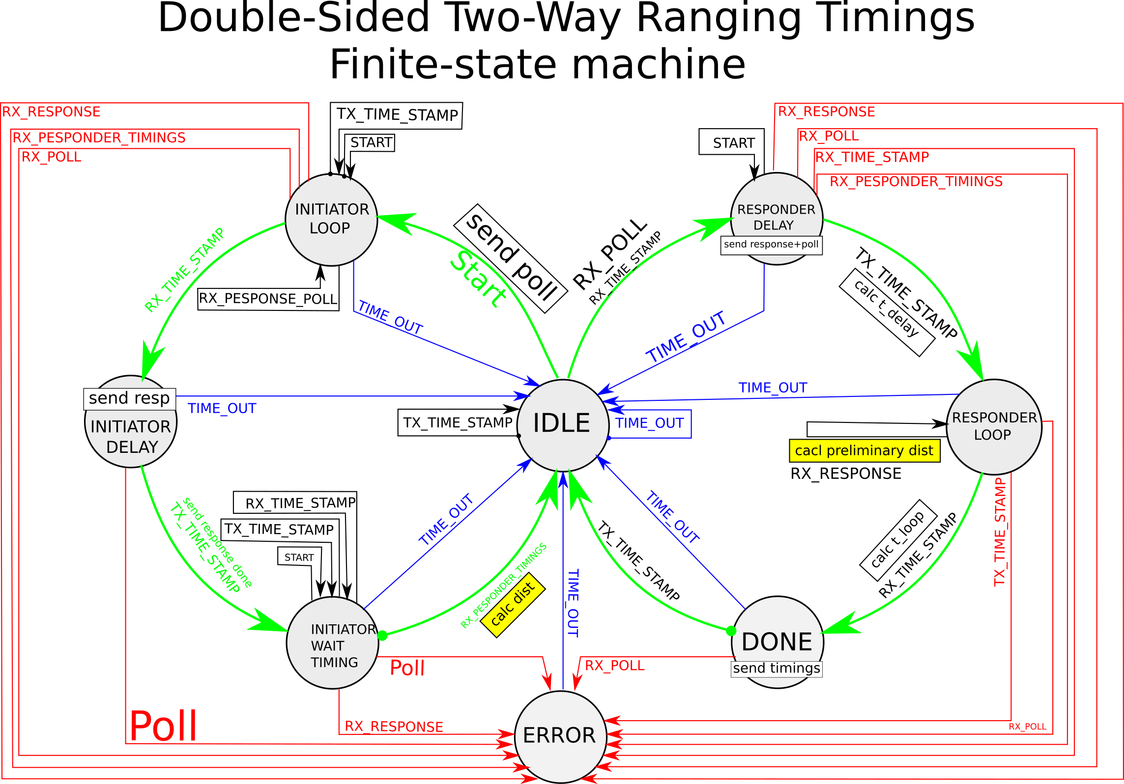
The thick line shows a successful execution cycle of the state machine.
If you run the DS-TWR protocol on DW1000 chips right out of the box, then the algorithm shows a distance greater than it actually is. About 155 meters, when in fact the distance is about 2 meters. The spec says that DW1000 transceivers need to be calibrated. It is worth noting that the measured ToF contains the signal propagation delay time in the antenna when sending and when receiving. Therefore, when recalculating the measured ToF into meters, a large number of meters will be obtained. The difficulty is that this internal propagation time also varies between DW1000 chip instances. It is also affected by passive components in the analog antenna circuit. To take this into account, the device is calibrated.

To calibrate the antenna delay, it is necessary to assemble an improvised stand. I had to not only program, but also draw, run around construction markets, drill, sharpen and, of course, sand. The result is this setup.

After the first experiments with UWB range measurement, the measurement accuracy was of the order of +-0.3 … 0.45 m.
Conclusion
If the transceiver allows you to determine the time of sending and receiving a radio signal, then you can calculate the distance between radio transceivers using the DS-TWR protocol. On modules DW1000 it is possible to measure the distance with an accuracy of the order of – + 45 cm.
Dictionary
Acronym | Decryption |
DS TWR | Double Side Two Way Ranking |
SS TWR | Single Side Two Way Ranking |
UWB | Ultra-wideband |
ASIC | Application-specific integrated circuit |
TOF | Time of flight |
TWR | Two Way Ranging |
Links
https://habr.com/ru/post/723594/
https://habr.com/ru/post/719542/
https://www.qorvo.com/products/p/DW1000