Sound customization: “lenses” from a metamaterial to control the sound field
When going to the cinema, the first thing we pay attention to is the picture. Bright colors, clear image without any flaws are of great importance for our perception of the film that we are watching. But do not forget about the sound. If its quality is lame, then whatever the picture, the viewing experience will be spoiled. Much more attention is paid to image quality: new screens, 3D glasses, cameras, lenses and much, much more are being developed. Today we will talk with you about the study, in which a group of scientists decided to correct this injustice. They paid all their attention, time and intelligence to the sound, or rather to the development of a new device capable of working with sound as with light. Telescope, magnifier, collimator and even varifocal lens, and all this with the prefix "acoustic". How exactly did scientists manage to achieve control over sound waves, what is their device, how difficult is it to create, and what results did it show during tests? We learn about it from the report of the research group. Go.
The basis of the study
Scientists note that the formation and control of sound fields is the most important component of modern technologies associated with sound reproduction. As a rule, this is achieved by controlling the intensity or phase of the source-sound generator using phased arrays. This method allows you to control the sound in real time, but devices of this kind are often cumbersome and expensive.
In turn, the light requires a different approach if we want to gain control of it. You can improve perception by means of related parts (filters, lenses, etc.). Changing the parameters of these elements allows you to get a certain type of device with its unique properties (cameras with autofocus, LCD displays, VR headsets, etc.). Such sound manipulations are not yet possible. If we want the best sound, we need large and powerful speakers, exaggeratedly speaking.
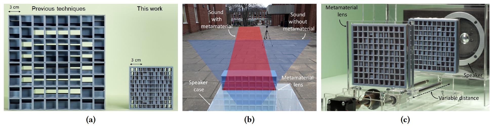
Image number 1: (but) – Comparison of previous developments (left) and described in this work (right); (b) – conversion of a standard column into a directional one; (with) – installation of a focused acoustic lens.
Metamaterials can help solve this problem. A distinctive feature of such materials is that their properties practically do not depend on the characteristics of the substances from which they are made. Where it is more important exactly how they are made, that is, what structure, architecture, topology, shape, etc. have. Unfortunately, the use of metamaterials in works with sound is not yet very widespread due to some difficulties: thickness that does not correspond to wavelengths; static device and a limited frequency range.
For scientists, these limitations are a challenge that they bravely accept. They developed a new method for designing metamaterials that resemble lenses, but not for light, but for sound. At the same time, we managed to circumvent the above limitations. How exactly we analyze in more detail.
Metamaterial Design
Researchers identify four main steps in the process of creating a metamaterial:
- the choice of its functions (what it should do with sound);
- converting this information to a similar phase / intensity distribution (2aa) on the surface of the metamaterial (hereinafter the meta-surface);
- selection of work cells (2a);
- creation of a meta-surface, taking into account limitations in terms of space and amplitude-frequency characteristics (2b).

Image number 2: (but) – comparison of two phase profiles; (b) – COMSOL transmission model cell # 15, scaled so that its base was 10.4 mm; (with) – the principle of operation of the cell type B.
It should be understood that the future function of the meta-surface will depend on how the distribution of acoustic pressure passed through the device will look. Accordingly, the geometry of the meta-surface and the intensity distribution play an important role.
Scientists obviously know that it is they who walk from their creation – to act as a lens, but for sound. The lens in this case will be characterized by two parameters: the focal length and the physical size (in the case of a meta-surface, how many cells the lens takes).
Once the desired focal length (f) installed along the axis of the lens (ˆz), the phase distribution φ (x, y) on the meta-surface (assuming that it is in the z = 0 plane) is obtained by asserting the fact that all contributions from the cells enter the phase at (0, 0 , f). For this particular work, scientists used a parabolic profile:
φ (r) = φ0 – BUT2(x2+ y2)
where φ (x, y) is the local phase related to the cell, A is a constant associated with the local curvature of the phase profile, λ0 – estimated wavelength, and φ0 – arbitrary constant.
The parabolic phase profile in optics allows us to obtain more compact lenses, therefore, the projected meta-surface will also be small in size. In addition, such a profile links the parameter A to the “curvature” of the lens, that is, the larger the A, the more focused the lens is (2a).
After establishing φ (x, y), it is necessary to choose which cells on the meta-surface will be involved. It is also necessary to take into account the fact that the smaller the frequency, the greater must be the cell.
In the study, a meta-surface model with 16 cells was used: rectangular cuboids ∼ 4.3 x 4.3 x 8.6 mm in size, designed for maximum transmission (∼ 97% of the input sound) with f0 ± Δf2dB = 40 ± 1 kHz. The easiest way to apply such a model at a different frequency (f) this scaling: change the size of each cuboid, until its thickness is equal to the new wavelength λ = s0/ f (where with0 ∼ 343 m / s – the speed of sound in the air).
With a new frequency, each of the cells applies the same phase delay in the range of 0 … 2π, while all of them have the same bandwidth as with f0.
Scientists note that cuboid designed for f0, has the same transmission and at other frequencies (2b). These frequencies are defined as follows:
fj = f0 – j ⋅ c0/ Leff
where j = 0, 1, 2 … N is an integer, Leff – design parameter of a specific cell, N = round (Leff/ λ0) – (integer) number of times when Leff contains a wavelength.
From this it follows that the cells can be operated at one of the frequencies fj (2c), supporting the transfer is comparable to that which is when f0.
During the test, the frequency f was used0 = 5.600 Hz. This frequency corresponds to a wavelength of 6 cm. It was chosen solely because of technical limitations (the 3d printer could not print larger cells). But, according to scientists, given the scalability of their model, this restriction during tests does not affect the conclusions.
Two types of lenses were used:
- Type A obtained by scaling the cells, so that their first resonance (j = 0) is 5.6 kHz, and the thickness is equivalent to λ0 (i.e. 60 mm). Each of the lenses of this type consists of an array of 8×8 cells, and the total size is 240x240x60 mm (1aon the left). Lens bandwidth is 2 ⋅ Δf2dB ∼ 0. 05 ⋅ f0.
- Type B obtained by scaling the cells, so that their second resonance is equal to 5.600 Hz. Each lens of this type consists of an array of 10×10 cells, and the total size is 104×104 mm with a thickness of 20.8 mm (1a, on right). The capacity of type B is also quite large. Calculations showed that it is 2 ⋅ Δf2dB ∼ 0.28 ⋅ f0. The main disadvantage of type B lenses is the following: given that the 16-cell model covers only part of the phase space, only a limited number of focal lengths can be realized with a fixed-size lens.
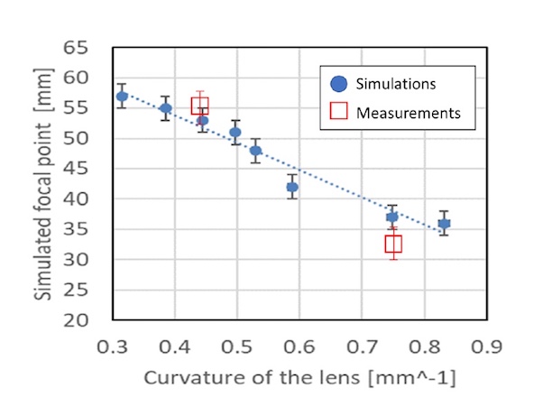
In the graph above, we can see the simulation results, which show that if a 10×10 lens is used, the maximum focal length will be 57 mm. That is, to increase the focal length it is necessary to increase the lens.
The main points of meta-surface design became clear to us. Now we turn to the description of how all this was implemented in practice in the form of prototypes.
Acoustic Collimator
The researchers, given the above achievements, were able to create an acoustic collimator – a system that corrects the geometric divergence of the source, with the result that the output sound is spatially represented as a beam. Simply put, the sound does not spread wherever it pleases, but forms a focused beam.
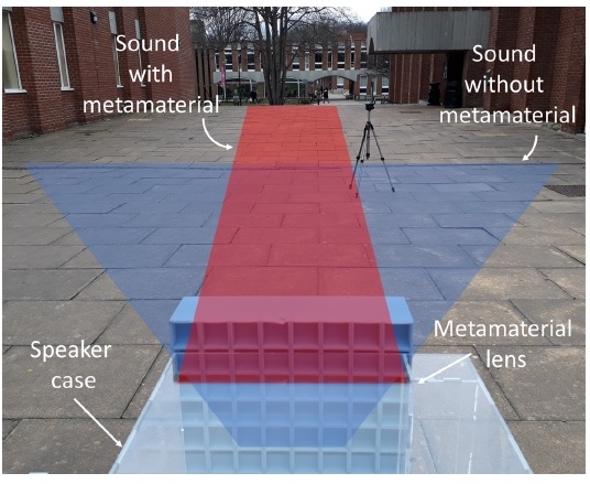
The picture above shows how sound is distributed without metamaterial (blue field) and with metamaterial (red field).
In optics, collimators are used in beacons for the projection of light over long distances, and in the production of searchlights. In such devices, the lens is located at a distance from the light source, equal to the focal length of the device, due to which the incident wave turns into a parallel beam.
In the case of an acoustic collimator, a type A metamaterial lens was located at a distance of 150 ± 2 mm from the sound source.

Image No. 3: Acoustic collimator performance and installation diagram.
Schedule 3a in the image above it shows that the acoustic pressure, measured at different distances from the sound source, is significantly greater with a lens than with it. The angular radiation, measured at a distance of 4.24 m, shows that the angle of divergence of the dynamics (sound source) due to the lens decreased from 60 ° ± 1 ° to 27 ° ± 1 ° (3b).
Also, scientists note that the lens from the metamaterial has changed the sound quality used in the experiments of cheap dynamics. At the same time, tests in the open air showed a significant increase in the distance of sound perception: without an acoustic collimator – 10 m, with a collimator – 40 m.
Scientists suggest that the angle of divergence can be made even smaller by more accurately adjusting the distance between the speaker and the acoustic lens (collimator).
How can you use acoustic collimator in life? The developers of this device have several options:
- Sound personalization – projecting sound exclusively to certain areas of the cinema hall (3s); different acoustic signals depending on the position in space (VR headset); creating different sound zones (for example, 3 people are sitting on the couch and each listens to their own, without disturbing the others).
- Increasing the performance of acoustic systems – at concerts and in cinemas they always try to optimize the sound so that everyone can hear everything, but there is a part of the audience where the sound is “incomplete”. On the image 3d 2 dynamics are shown, symmetrically directed in different directions. In this position, there is a gap where the sound will be bad, roughly speaking. Using the acoustic collimator installed in this gap, you can fix it.
- Improving the spatial sensitivity of acoustic sensors.
Acoustic Magnifier
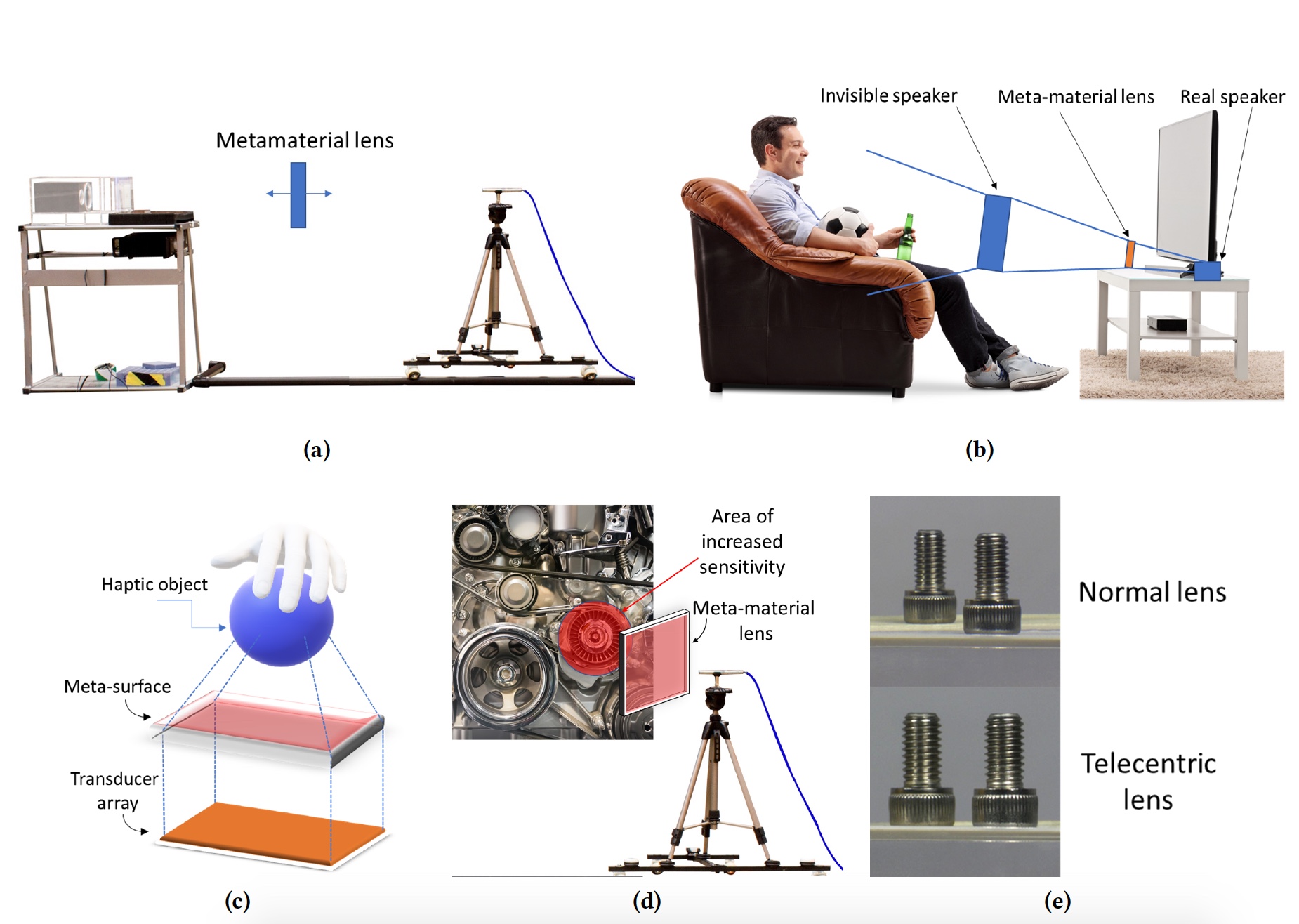
Image number 4: diagram and photo installation acoustic magnifier.
We all know the essential attribute of the image of a detective – a magnifying glass or a magnifying glass. We look through a magnifying glass at something and see this object in an enlarged view. The same thing happens with sound, if you apply an acoustic magnifier. In the test setup (4a) scientists have placed a metamaterial (magnifier) between a microphone and a speaker. The position of the magnifying glass was adjusted to achieve the maximum signal received by the microphone. Due to this, the weak sound is enhanced.
The scope of application of the acoustic magnifier is also not limited to one option:
- Changing the position of the source – on the diagram 4b An example is shown: a man sits on a sofa in front of a TV with a built-in speaker. If you apply an acoustic magnifying glass, it creates the feeling that the speaker is in front of it.
- Expanding the capabilities of tactile devices (touch feeling in the air, video below). Such technologies are directly related to sound, but are limited in the maximum distance between the “virtual” object and its generator. An acoustic loupe can increase this distance.
Tactile technologies create a sense of touch through sound.
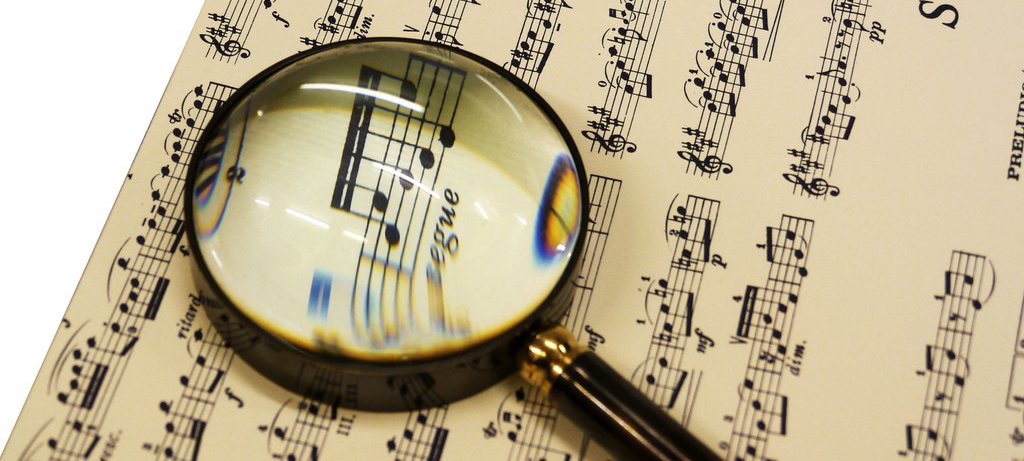
- Improved sound reception – an acoustic lens can change the spatial characteristics of a microphone. On the image 4d shows the use of an acoustic magnifier to focus attention on a particular object, surrounded by many others. Simply put, such a magnifying glass will allow you to listen only to what is necessary for you, sifting out all the accompanying and background noises.
- Align sound levels from different sources. Imagine that you are talking to two people in a large room. One interlocutor is nearby, the second is far away. An acoustic loupe would allow you to hear both interlocutors in the same way, as if they both were at the same distance from you (a visual example in the image 4e).
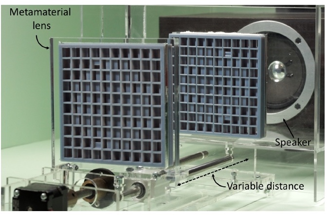
Acoustic Telescope
Telescopes are needed to explore what is very far away. The banal and exaggerated statement, but from that it does not lose its veracity. Telescopes operate by two lenses located at a certain distance from each other. The acoustic telescope also uses a similar principle.
Above is a photo of the installation of the acoustic telescope: two lenses from the metamaterial, the distance between which can be changed with an accuracy of 1 mm, and the speaker.
The main advantage of the telescope is that it can bypass the limitation of the focal length of one lens, because it uses two, and the ability to change the distance between them allows you to change the focal length.
Image number 5: installation of the acoustic telescope and an example of application.In practice, the acoustic telescope allows you to hear the sound coming from a long distance, and isolate it from many other sounds. On the image 5b It is shown that the acoustic telescope allows you to hear a person in a crowd at a great distance. We could observe such things in spy movies.
For more detailed acquaintance with the nuances of the study I strongly recommend to look into the report of scientists, available at this link or this.
Epilogue
Summarizing the above, the researchers were able to create a simple and effective device that allows you to manipulate sound. Focusing the sound at one point, leveling the sound from two sources, isolating a certain sound, eliminating noise, amplifying the sound – all this can be done through a lens from metamaterials, more like a vent plug or baking waffle mold.
This work demonstrates that an accurate understanding of the nature of a phenomenon, physical, chemical or biological, allows one to gain control over it and to change its properties as the situation requires. How exactly will be used acoustic lenses can only guess. The scientists themselves are not going to stop there and will continue to research in order to improve their offspring.
Friday off-top:
If we talk about the fauna, then the bird lyrebird best understands the sounds, or rather, imitation of a variety of sounds. This particular male seems to be a Star Wars fan.Off-top 2.0 (musical):Similar Posts