Assembling a compact 40% Velvet keyboard
Foreword
Velvet is a small, compact keyboard.
Fully in open accessso that every DIY enthusiast can try to assemble the keyboard by themselves.
Curved and ergonomic 3D design – all in the best traditions of ergonomics.

Required components to assemble the keyboard:
Microcontrollers Raspberry Pi Pico (We Act Studio) – 2 pcs.
Single PCB (hotswap) boards – 38 pcs.
PCB holder for the controller – 2 pcs.
3D case, bottom plates – 2 pcs.
Kailh hotswap sockets – 38 pcs.
Diodes smd 1n4148w – 38 pcs.
Resistors: 10kOhm – 4 pcs. / 5kOhm – 2 pcs.
TRRS connectors – 2 pcs.
Wires: 10 cm – 4 pcs. / 8 cm – 14 pcs.
Screws: M2x5 – 6 pcs
Silicone feet – 8 pcs.
Jumpers can be made with copper wire or legs of through diodes / resistors
TRRS and USB-C cables
MX switches 38 pcs.

Required tools:
Assembly order
Preparing boards for installation
Board mounting
Jumper setting
Mounting the microcontroller and TRRS connector
Keyboard Firmware
Holder installation
Collection of the left half
We prepare boards
First you need to prepare the boards. To do this, we apply solder to the pads on one side, so that it is easier to solder the components.

Next, you will need to solder the diodes and hotswap sockets to the boards.
Diodes have polarity and therefore it is important to install them with the correct side. The cathode is marked with a white line on the diode. The boards also have silk-screen printing with the same line. We solder “line to line”.
All diodes must be installed in the same direction (cathode down).
Hotswap sockets are installed in the hole and soldered.

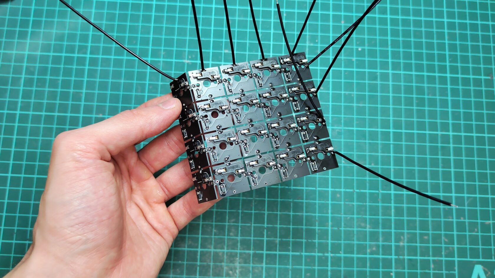
Next, you need to solder the wires to the boards, as shown in the figure below. The 10cm wires are marked in red. It is also necessary to apply solder to the jumper pads on all boards (marked in yellow).

Board mounting (right side)
We carefully “break off” the boards.
We substitute the board to the case and install a switch in it so that the board holds.

Boards with wires should be located around the perimeter (top row and side column under the cluster)
Jumper setting
We use ordinary 1n4148 diodes as jumpers, cutting them off on both sides. You can also use copper wire.
We connect together first the columns (Col) then the rows (Row).

To avoid a short circuit, make sure that the row jumpers do not touch the speaker jumpers.
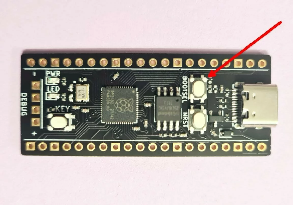
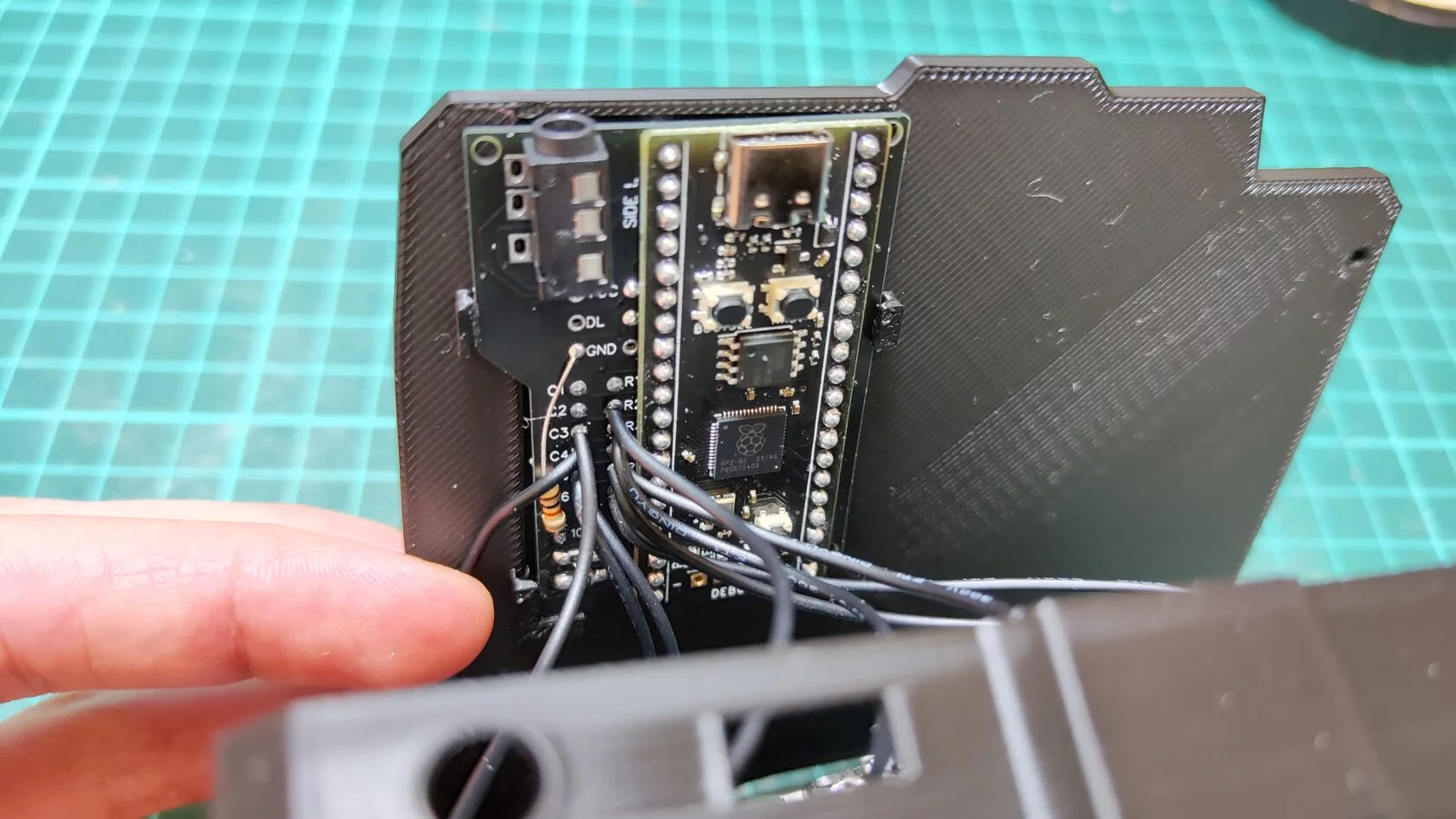
Mounting the microcontroller and TRRS connector


We install the controller on the holder, leave a little space to the board, as in the figure, so that later you can press the controller to the board and cut off the rest of the pins with wire cutters.
We solder one contact on each side, as in the figure.

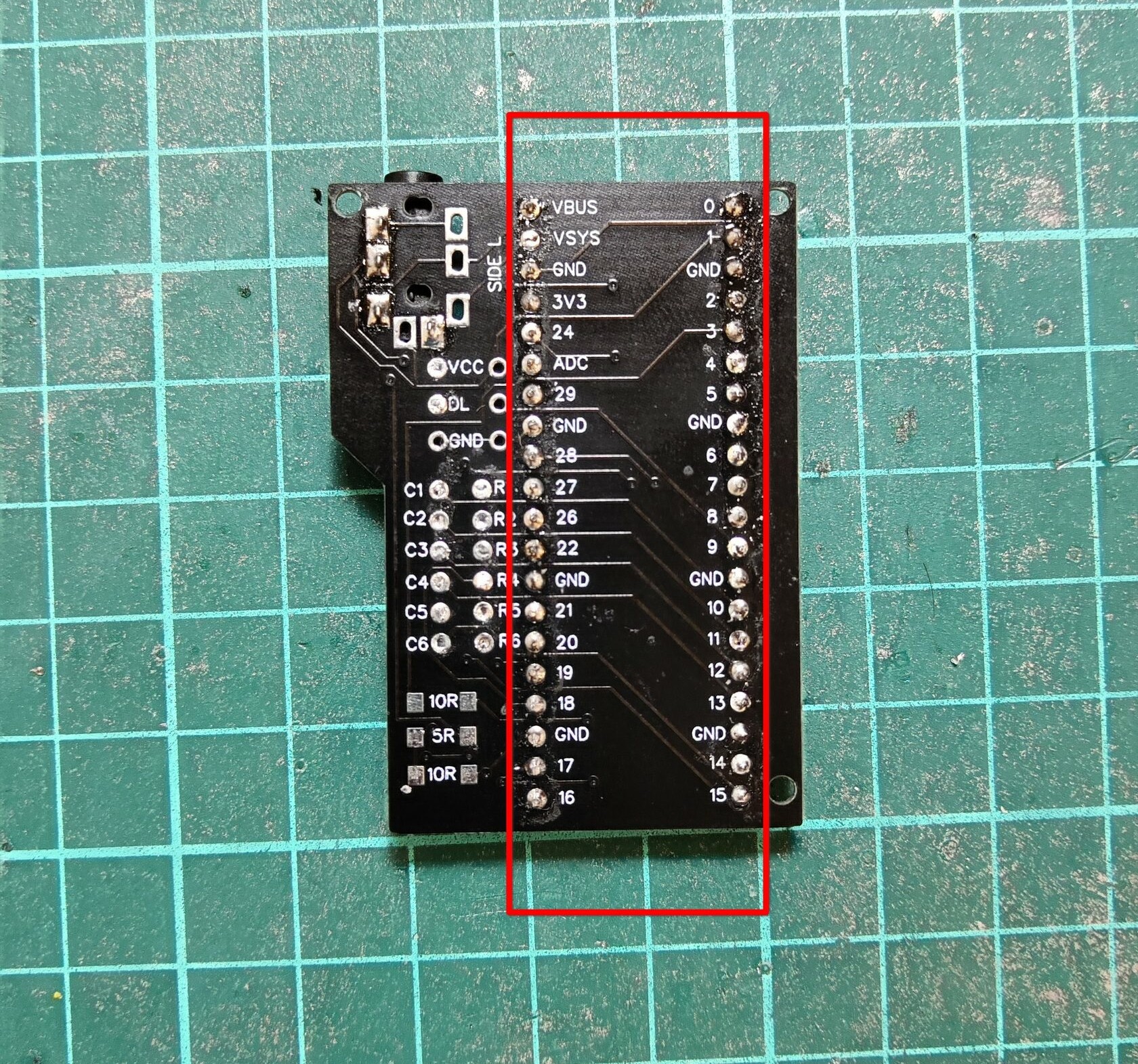
Next, we press the controller to the holder and solder the rest of the contacts.
After soldering all the contacts on one side, turn the controller over and bite off the rest of the legs with wire cutters.
Next, solder the pins on the second side.
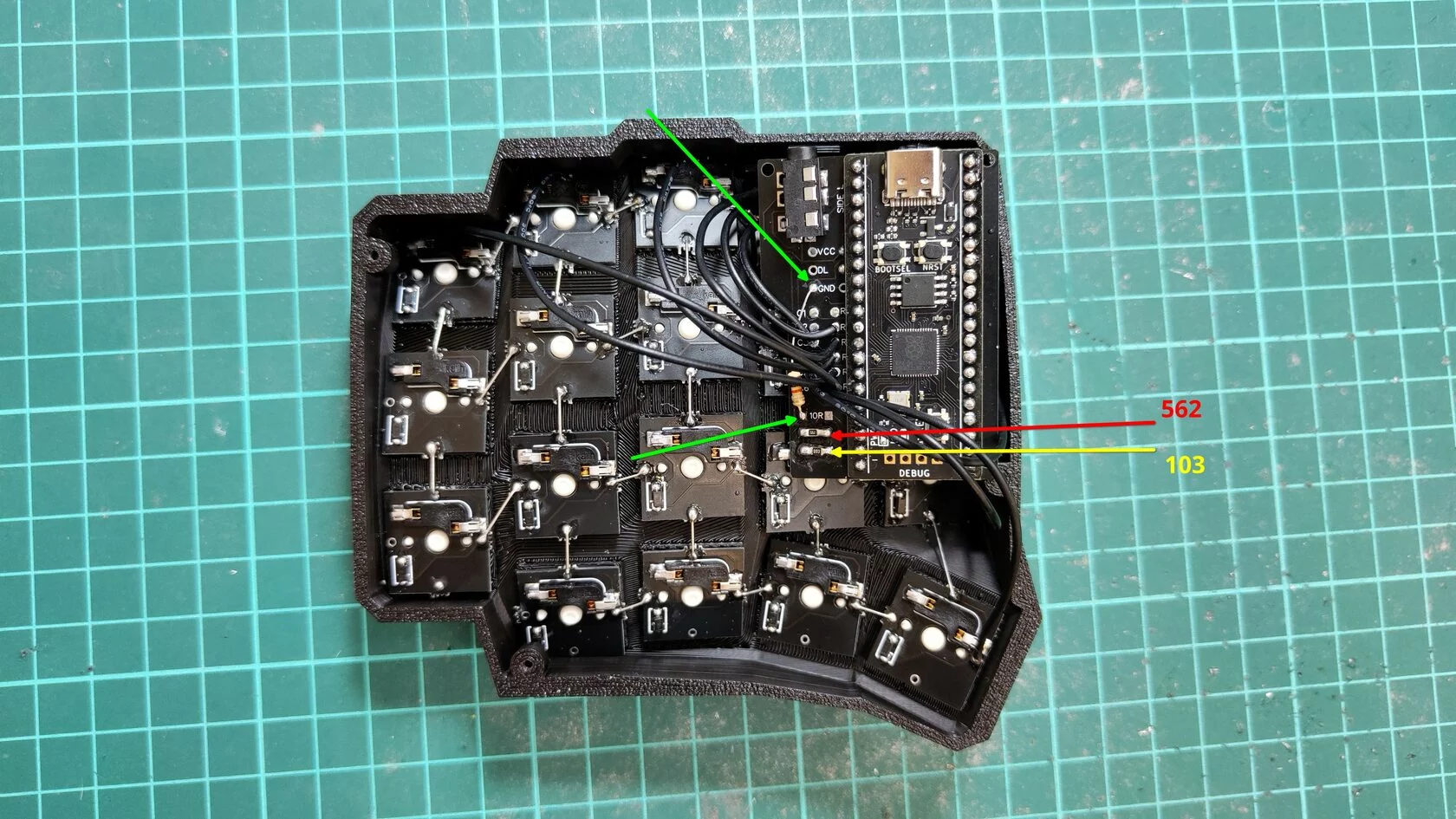
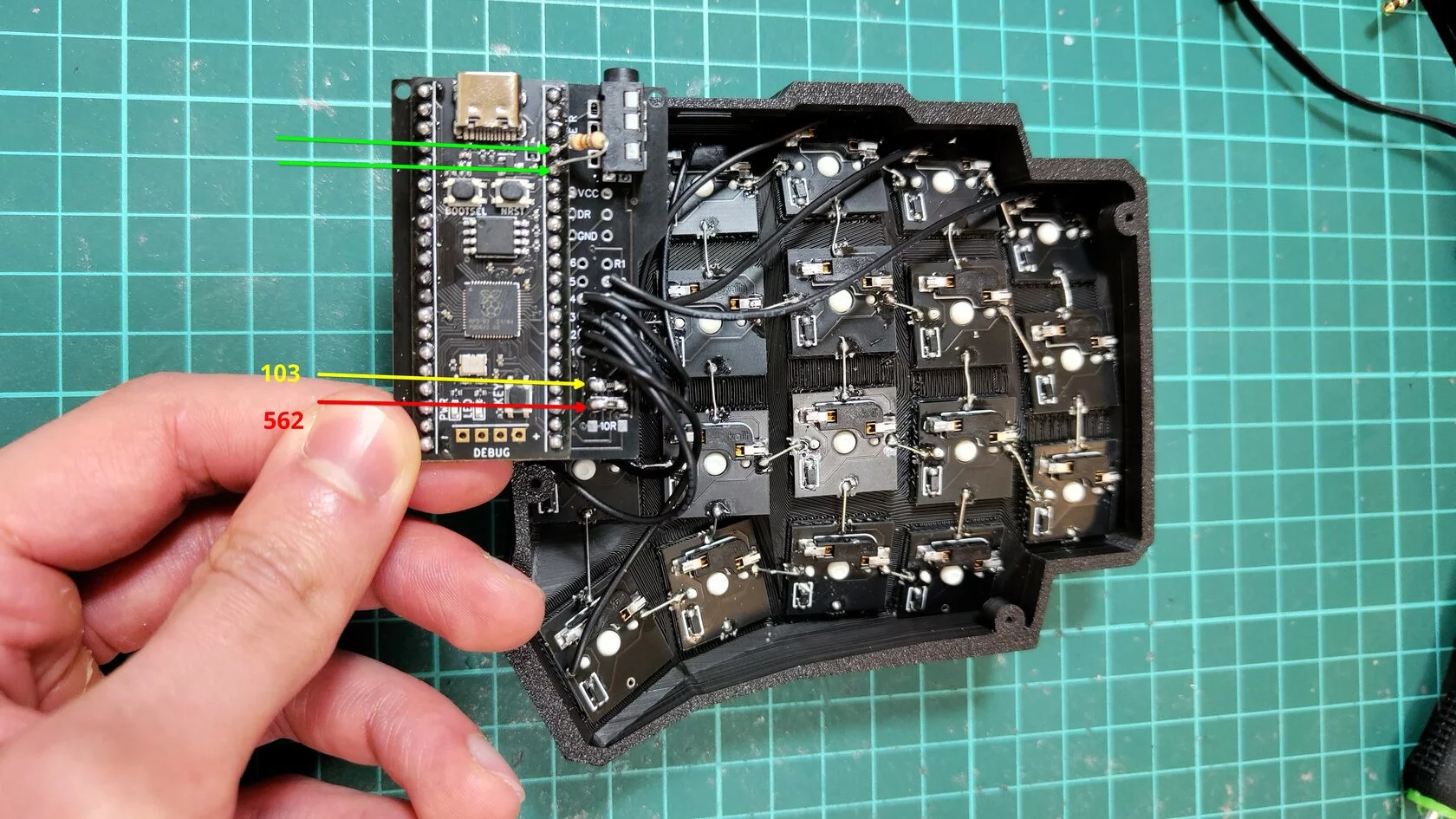
We begin to solder the resistors, as in the figure below. (right side)
Red marks the installation site of the CMT resistor marked 562 (no polarity)
Yellow marks the installation site of the CMT resistor marked 103 (no polarity)
Green marks the soldering points of the 10 kΩ resistor (no polarity). We bite off the legs of the length we need and solder the resistors, slightly moving it to the side, as in the figure, so that it does not interfere with the further installation of the wires. One leg to Gnd, the other to left pad 10R.
After that, install the TRRS connector.
Then we begin to solder the wires to the holder.
Solder as in the picture. (right side)
Carefully cut the protruding ends of the wires.
Keyboard Firmware
Until we screwed the covers, it is necessary to flash the keyboard and check the keys for operability.
We hold down the Bootsel key on the microcontroller and connect the USB. After connecting, release the key. The microcontroller should be defined as a USB drive.
Drag Uf2 onto it firmware file.
The microcontroller is flashed.
Holder installation
Install the holder in the hole in the bottom plate.
We do not fasten the bottom cover yet, since we need to assemble the Left half, check the keyboard, and only then tighten the M2 cover with screws and install silicone feet.
Collection of the left half
The left half is assembled in the same way, except:
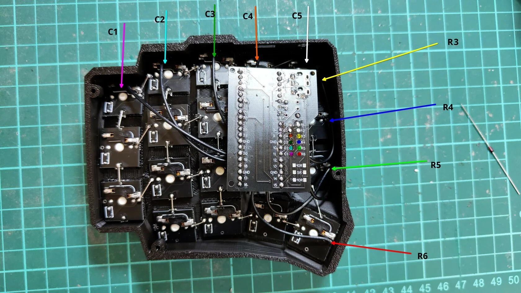
We cut the resistor a little on both sides and install it on pins 3v3 and 24 on the microcontroller itself (4 and 5 in a row, marked in green) and bend it slightly to the side so that it does not touch the boards, as in the image.
We also install CMT resistors in accordance with the image below.
We solder the wires in accordance with the figure below.

After we soldered all the wires, we flash the microcontroller on the left half.
Next, we will need to check the keyboard:
We connect the halves with each other with a TRRS cable
Connect USB cable
We go to Vial
Click on the “Matrix tester” menu, then “Unlock” and follow the instructions on the screen to unlock the keyboard
Checking every key
If all the keys work correctly, then we twist the bottom covers, install the silicone legs and enjoy the ergonomics!

How to work on such a small keyboard?
The main advantage of 40% of keyboards is compactness and ergonomics, the curved body provides a more natural position of the hands and when typing, the wrist may not move at all – all actions are performed only by the fingers.
Many people may not like that on a keyboard with a small number of buttons, neither the number row nor other “useful” keys fit. However, thanks to the firmware, any key can perform any action or act as a modifier. Three or four actions can easily be assigned to each split key.
The possibilities of programmable keyboards are really impressive, with a little practice you can create the layout of your dreams.
Of course, getting used to such a keyboard will take some time. Nevertheless, the comfort in work, incomparable with ordinary keyboards, will overcome any inconvenience.
Github with sources.
Telegramwhere I will be happy to answer questions.