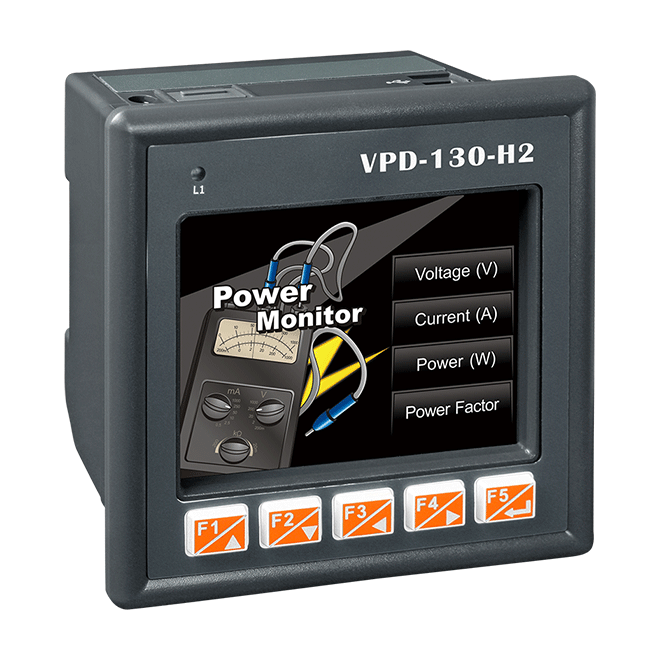
Writing a Modbus RTU Master module for VPD-130-H2 in HMI Works
Where it all started. I was given the task of connecting the VPD-130-H2 panel with 2 DC1-344D1NN-A20N frequency converters. The panel and frequency converter have a built-in RS485 interface, so I will use the Modbus protocol for control. In this case, the frequencies will act as Slave devices with addresses 11 and 22, and the panel will act as a Master device.
In this article, I focused on setting up an HMI panel and writing a module in C. Working with frequency converters will not be considered.
HMI Works is a software tool designed for developers working with TPD and VPD touchscreen controllers from ICP DAS USA. This software is based on HMI, Ladder Logic and C language. It is the main tool for working with the VPD-130-H2 socket.

A special feature of working with HMI Works is the presence of built-in modules for controlling external devices. The module specifies which variables should be created and how they are processed. It also specifies which interface and protocol is used for this device, which register addresses need to be read or written.
Since I didn’t find a module to control my frequency converter, I had to figure out how to write it from scratch. And this became a problem, I did not find documentation about which internal functions are responsible for what. In the official documentation there are only superficial mentions focused on the fact that built-in modules will be used. As a result, the idea of writing this article appeared.
Let’s start by installing software for working with the HMI panel.
Download the latest version of the software for our panel, as well as an update for it. https://www.icpdas.com/en/download/show.php?num=944&model=VPD-130N-H2

After installing the software and driver (installed along with the software), create a new project, specify our panel

Let’s move on to the panel itself. You need to enable the “USB Force Update” mode (in my case, the position of the knob is 9), this mode allows you to record the program into our panel.
An important clarification: before loading the program, you must turn off the power to the panel, then turn it on again and only then load the program, otherwise an error will occur in HMI Works

As mentioned earlier, modules are needed to communicate the panel with other devices. For my tasks, the default built-in modules are not enough, so let’s move on to writing it.
Writing a module
In order to add your module to the list, you need to follow the installation path of your program to the folder bin/ModulesI have C:\ICPDAS\HMIWorks_Standard\bin\Modules. Let’s look at the file Modules.ini. It indicates the series of devices, as well as the protocol through which the devices communicate.
Let’s add the name of the module to this list, in my case Frequency

In the same file we will write the protocol through which our module will communicate. Frequency – the name of our module, MRTUM – Modbus RTU Master protocol

You can customize the rest of the settings at your discretion.

In the same folder (where the file is located Modules.ini) create a folder where we will write the configuration of our device.

Inside the newly created folder we will add a file Frequency.ini where we write down the Model of our device (Frequency_motor), as well as its tags (tags are of WORD type by default)

It remains to describe the behavior of our Model. Create a folder with the device name (Frequency_motor)

Inside Frequency_motor we will add the IO.hsf file, which specifies the behavior of the module (sending, receiving data, processing tags) in C.
Since tag processing is different for each device, I will only mention some important functions, my entire project is available at the link at the end of the article.

Adding a new device
Let’s move on to our project tree. The first thing to do is create a new connection. Right-click on Connection and select New Connection. Here we can select the necessary protocol parameters and the port on which communication will be carried out, in my case everything is as it should be. Click OK and move on.

Now you need to add a new device. In the project tree, right-click on the Device inscription and select New Device. Here we can select our newly written module.

In TouchPAD is we indicate our communication interface, that is Modbus RTU Master (when we registered the configuration, we indicated Protocol=MRTUM). If we did everything correctly, then our module should appear in Device Series Frequency. Next, we indicate the Connection that we created, and in the Model Name we select the model frequency_motor. Now we can give an arbitrary name and identifier of the slave device, I have a device with Id 1. As we can see, on the right is a list of tags that we registered in frequency.ini.
Loading a project into the panel
Uploading the project takes place in 3 stages:
Assembly or render (Render), here the compiler reads the IO.hsf files, replaces the tag pointers that begin with the $ sign with the value tag + module name that we assigned. That is, the compiler will replace $SPEED_GET in the code with Frequencymotor_1_SPEED_GET. This way we can add dozens of identical modules, and they will not conflict.
Compile, here there will already be a check for syntax errors, and if there are none, then assembly of the code into a language understandable to the panel itself
Download, here the newly compiled code is loaded into the panel itself; before loading, you need to reboot the panel by de-energizing it for 1-2 seconds.

Conclusion
I talked about some of the pitfalls when working with the HMI Works program. We also figured out how to write a full-fledged module for working with Modbus devices. An example of a finished project is on gitHub.


