Two-pipe heating systems of dead-end and associated type. The imaginary magic of the “Tichelman loop”
Two-pipe heating systems of dead-end and associated type. What is the difference and what modern building codes say about it.
Earlier in one of the articles I already talked about single-pipe heating systems.
Now it’s the turn to consider the features of the design and operation of two-pipe systems, which are extremely popular among private homeowners in individual housing construction.
They are also trying to use two-pipe vertical riser heating systems in apartment buildings.
Next, we will consider the hydraulic calculation of systems for one floor of a private house with a perimeter of the same 50 m for a house 10×15 m along the internal walls (150 sq. m per floor).
And later we will try to apply the same approaches for a maximum height of 50m in the riser system of a high-rise building.
Dead-end system
A dead-end heating system diagram is a scheme where the supply and return pipes exit from the same starting point, and the pipes themselves run parallel to each other.

Fig.1. Schematic diagram of a horizontal two-pipe dead-end heating system (top) and a diagram of the flow of coolant in it (bottom).
Associated scheme
A parallel heating system diagram is a scheme where the beginning of the supply and return pipes are located at different ends of the system, the pipes themselves run parallel to each other, and the coolant in the pipes flows in the same direction.

Fig.2. Schematic diagram of a horizontal two-pipe associated heating system (top) and a diagram of the movement of coolant flows in it (bottom).
Theoretical calculation
For simplicity of calculation, we assume that the main distribution pipe (“riser” or “lounger”) has the same diameter along its entire length.
In a one-story private house, individual housing construction, a “lounger” is more typical, laid openly along the baseboard at the bottom of the outer wall (or walled up in the floor screed).
Next, we will combine “riser” and “bed” under one word “collector”.
Then, with a uniform distribution of heating devices along the length of the collector with a step of 3 m, we obtain a system of 16 radiators with 15 intervals between them.
16 radiators correspond to both the height of a standard 16-storey section of a multi-storey building with a height of 50m, and the cutting of a facade 50m long along the perimeter into standard rooms 3m wide along the facade in a one-story private house.
For hydraulic calculations, we will assume that the collector is straight with equal intervals between the radiators, and the radiators themselves will be assumed to have the same thermal power.
Then we get an extremely simple calculation scheme, where the flow rate through the collector changes stepwise by the same amount of 1/16 of the total flow rate, having a constant coolant flow rate in 3-meter sections between the radiators (see Fig. 3.)
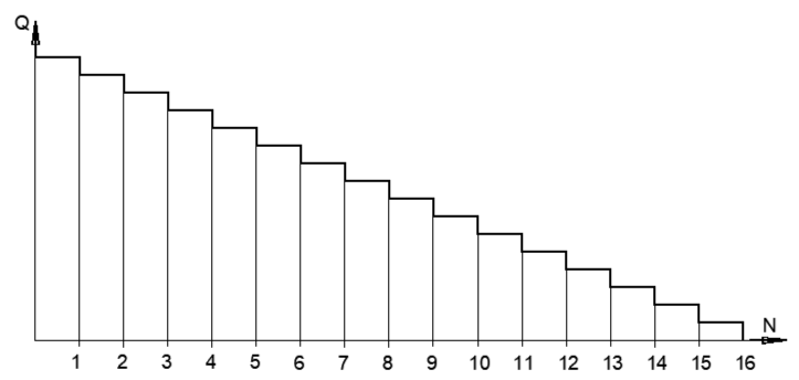
Fig.3. Step graph of coolant flow through the heating collector between the outlets to the radiators.
The pipe resistance is taken according to the nomogram for the zero section in front of 1 radiator, where the flow rate is maximum and falls within the zone where the nomogram is determined (see Fig. 4.). We take the resistance of the remaining sections as a quadratic function of the flow rate from the flow rate of the zero section.
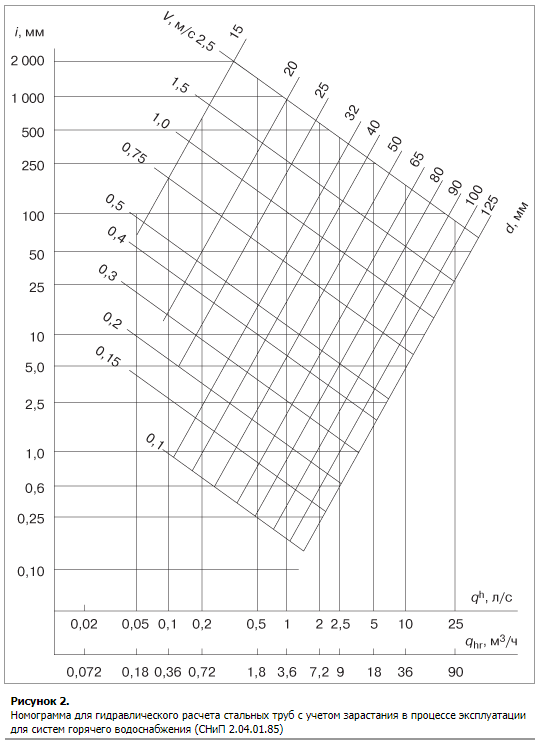
Fig.4. Nomogram of hydraulic resistance of steel pipelines with hot water.
We will take the collector from a steel pipe DN25 (one inch), which will most likely be the right solution.
Let’s write down the parameters of each section from 1st to 15th in the table.
Based on the result of the calculation, we obtain a table of values (see Fig. 5), based on which we will construct a series of graphs.
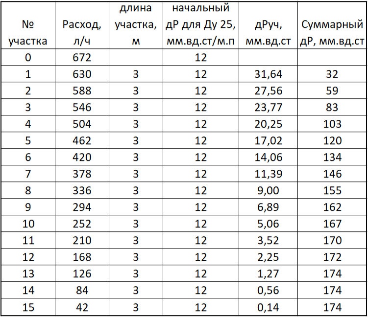
Rice. 5. Calculation table for one collector for 16 radiators with 15 calculation sections 3 m long. The final resistance of the direct collector is only 174 mm water column. It is interesting that the last 2 sections gave a total increase of less than 1 mm of water column, which did not change the value of the final resistance in the last 3 lines.
The dead-end circuit for the forward and return pipelines has the same graphs, so they coincide, and their sum has twice the values (see Fig. 6.)
For the associated circuit, the supply and return manifolds have a mirror appearance, and their sum looks like a symmetrical hump with a maximum in the middle (see Fig. 7)
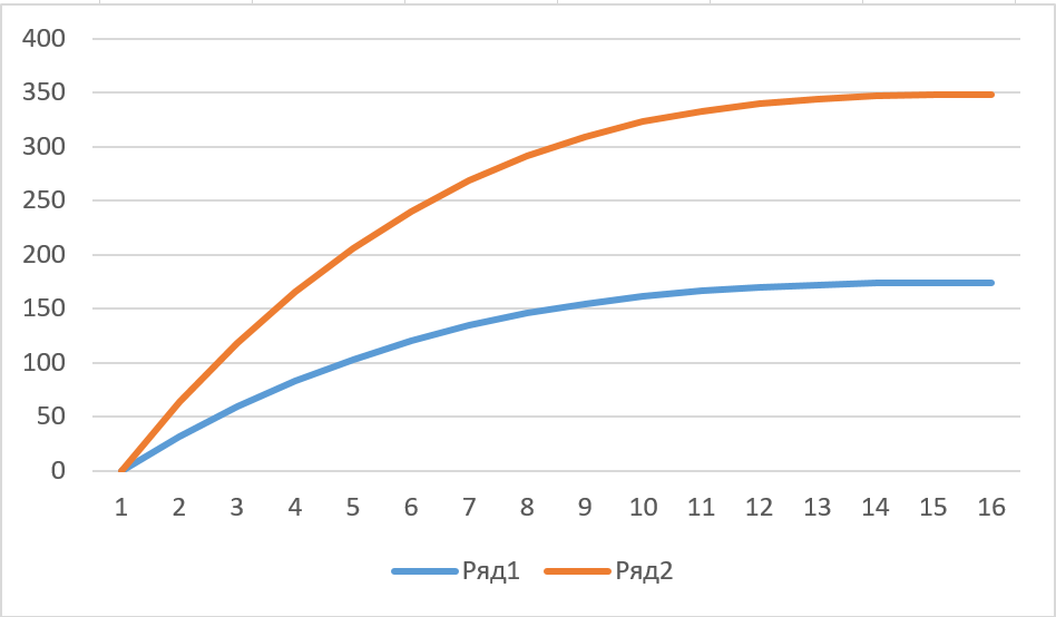
Fig.6. Graphs of losses on the forward (reverse) collector and the sum of losses (top graph) for each device from 1st to 16th
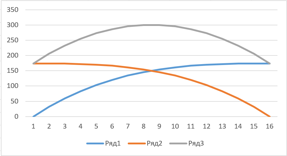
Fig.7. Graphs of hydraulic losses on the supply (orange) manifold and return (blue) and the sum of resistances (gray) for each device from 1st to 16th. Judging by the resistance hump in the middle on the gray graph, the flow into the middle devices is less than into the outer devices in the downstream circuit.
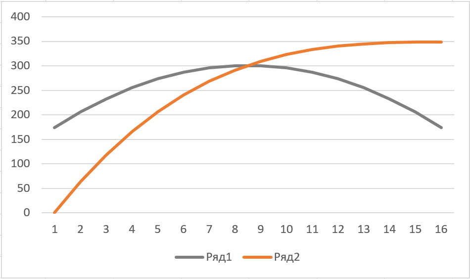
Fig.8. Graphs of total hydraulic losses in a dead-end circuit (orange) and a passing circuit (gray) for each device from 1st to 16th. It can be seen that for a dead-end scheme the difference between the maximum and minimum value is (350-0) = 350 mm water column, and for the passing scheme the difference is (300-175) = 125 mm water column.
To make it easier to evaluate the final differences, the total resistance curves of the dead-end and associated circuits are summarized on one graph (see Fig. 8).
According to the joint graph, it can be seen that the magnitude of the imbalance between individual radiators in the associated circuit is significantly less than in the dead-end circuit.
Specifically for this design scheme, the ratio of maximum imbalances is 350/125=2.8.
Moreover, in the associated circuit, none of the radiators had zero resistance, and the difference between the edges and the middle in resistance had a ratio of 300/175 = 1.71.
Such a pressure difference meant a flow discrepancy in an even smaller ratio, or rather in a square-root relationship:
1.71^0.5=1.31
Thus, in the associated circuit without adjustment, the maximum difference in flow rate was only 31% at maximum, or +/- 15% of the average value.
For such a simple and reliable system, this is an almost ideal result, and even this 15% can be compensated by increasing the power of the 6-section cast-iron radiator by 1 section in the middle of the system.
To finally consolidate the superiority of the associated circuit, it is necessary to take into account the resistance of the supply pipes to the radiator and the radiator itself, which will evenly raise the entire curve upward without changing its shape
Such a rise, even by a small amount, will greatly reduce the error in the flow distribution across the radiators.
Under given conditions, the resistance of one cast iron radiator with DN15 connections (half an inch) will be about 10 Pa, which will change the distribution from an error of 15% to 14.5%
To reduce the distribution error among radiators to +-10%, it will be necessary to increase the resistance of an individual radiator to 100Pa.
This value can be achieved by installing a local narrowing in the form of a bushing in one of the pipes leading to the radiator.
The diameter of such a sleeve should provide a velocity head of 100 Pa at a flow rate of 42 l/h.
Thus, a resistance of 100 Pa will create an acceleration of the flow to a speed of only 0.45 m/s, which is ensured by a bushing with a diameter of Ф6 mm installed in front of the radiator.
The total resistance of the system will be 300+100=400Pa.
In this case, the gravitational thrust of the boiler at a difference of 1 m (the pit for the boiler is 1 m below the floor in the house) with a temperature difference in the pipes dT = 20 C will be only 120 Pa (12 mm water column).
That is, for a network resistance of 400 Pa, you need to lower the boiler deep into the basement with a height difference of about 3.5 m.
Optimization of the gravity heating system of a rural house
To get by in a house without a boiler room in the basement, it is necessary to increase the diameter of the collectors, which will reduce length losses.
Thus, the transition from a diameter of DN25 to a diameter of DN 40 (one and a half inches) will reduce the starting resistivity of the collector by 12 times from 12 Pa/m.p. to 1 Pa/m.p. (see figure). As a result, the resistance ratio will be 25/14 Pa.
In this case, the resistance of the radiator with liner will remain unchanged at 10 Pa (see Fig. 9)
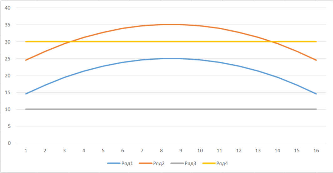
Fig.9. Graphs of the total hydraulic losses in the associated circuit for each device from 1 to 16: blue – collector resistance, orange – collector resistance with the addition of 10 Pa from the radiator, gray – basic level of radiator resistance (10 Pa); Yellow is the average line of reference for the discrepancy, which is only +-5 Pa.
With such a sharp drop in the collector resistance, the share of the constant resistance of the connections will increase sharply, ensuring the necessary balancing of the network without additional narrowing in the connections.
35/24=1.46
In this case, 1.46^0.5=1.21 or +-10.5%
That is, the resistance of the connections to the radiators will be more than enough for almost perfect balancing of the system with an error of +-10% in flow rate.
The total resistance of the system will ultimately be less than 50Pa, which is ensured by a difference between the boiler and the return manifold of about 0.5 m.
A difference of 50 cm can be easily achieved with a small pit, or by placing the combustion boiler in the entryway at ground level.
It was according to these schemes that heating was done in rural private houses in the USSR in the second half of the 20th century, when pipes and cast-iron radiators began to reach the villages, and the villagers themselves began to live a little richer and gravitated towards urban comfort in heating.
It is especially worth noting that gravity heating systems worked well in 2-story buildings, since the height difference between floors provided a high gravity-circulation pressure in the system.
True, such heating systems in two-story houses turned rather into single-pipe riser systems.
So the supply manifold was located on the 2nd floor under the ceiling, and the return manifold lay on the floor of the 1st floor. The collectors were connected by two radiators in a series vertical riser, often without even bypasses on the radiators. (see Fig. 10)
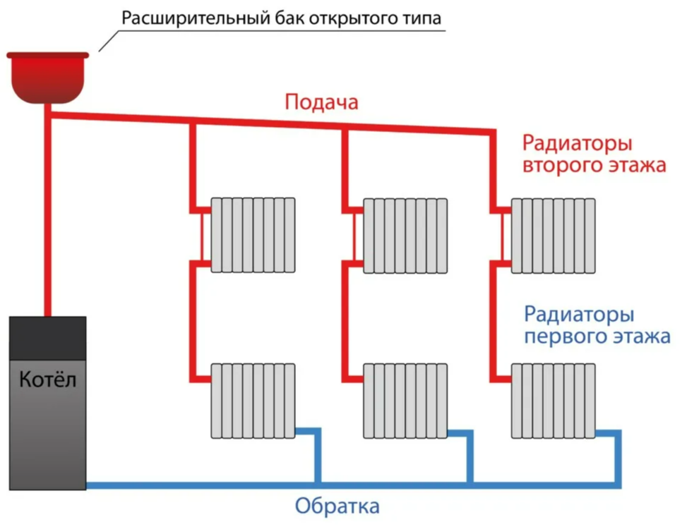
Fig. 10. Scheme of a heating system with gravity traction in a two-story house.
Calculation of a dead-end two-pipe for individual housing construction.
It turns out that the passing circuit is initially configured better than the dead-end circuit?
This is not entirely true, since in the same conditions of a rural 1-2-story house, a heating system with large-diameter collectors may have variations that nullify the “magic” effect of the associated circuit.
Initially, according to the calculation, the maximum resistance of the Du25 collector in the dead-end circuit was 350Pa versus 300Pa for the companion.
When switching to a diameter of DN 40, the resistance dropped by 12 times, that is, to a value of 30 and 25 Pa, respectively.
Having a balancing resistance of only 10 Pa on the radiator, self-adjustment of a dead-end system will be
40/10=4
In this case, the imbalance in consumption will be:
4^0.5=2 times or +-50% of the average
It would seem a catastrophic difference in favor of the passing scheme!
Yes, in this formulation of the problem, a ride wins over a dead-end scheme, but there are nuances.
In the case of transition from a ring ride-hailing scheme to a dead-end scheme, the situation changes radically with small changes in the structure of the system.
So, in a dead-end circuit, instead of a long ring, you can make two half-branches by cutting the ring in the far section and attaching two counter branches to one original node (see Fig. 11)
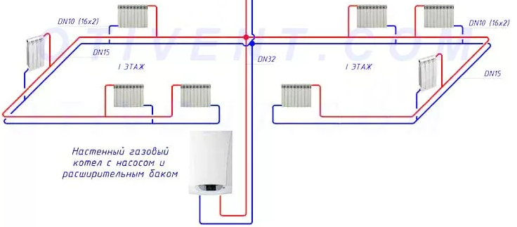
Rice. 11. An example of a cut horizontal hitch ring into two half rings according to the dead-end option.
If you do not change the diameters of the collectors, then the coolant flow rate in the branches drops by half and their length is reduced by half, which ultimately leads to a drop in the total resistance of the collectors by 8 times (2 cubed) from 350 Pa to 44 Pa even in the variant with collector DN25.
Cubic dependence is a very cool growing function!
This can be visually assessed by the following volumetric graphic interpretation of the digital calculation (see Fig. 12)
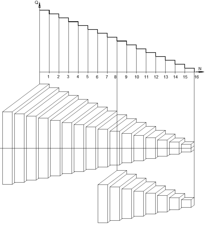
Fig. 12. Step flow graph and volumetric pyramids of the resistance function of one collector. The volume of one stage is equal to the resistance of this section of the collector. The total volume of the pyramid is equal to the collector resistance at its full length. Large pyramid – full length in a ring, small pyramid – half length in a ring cut in half for a dead-end scheme. The volume of the pyramid is equal to the area of the base by 1/3 of the height. Since the volume is proportional to a cube of linear size, a pyramid with half the height will be 2^3=8 times smaller in volume.
In the case of carrying out the same trick with cutting the ring with a DN40 collector, the resistance drops 8 times from 25 Pa in a full ring, and to 3 Pa in a half ring.
As a result, taking into account the balancing resistance of 10 Pa on each radiator, we obtain a hydraulic pressure discrepancy:
(10+3)/10=1.3
In this case, the consumption discrepancy will be:
1.3^0.5=1.14 or +- 7%, which is even better than +-10.5% for the parallel scheme with a full ring.
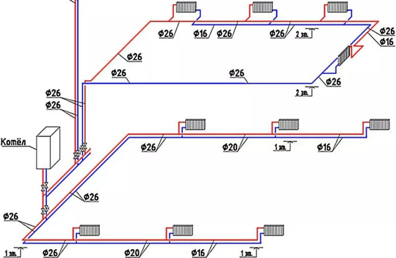
Rice. 13. An example of a project where in one house both a dead-end scheme (on the first floor) and an associated scheme (on the second floor) are simultaneously used. The feasibility of using a passing scheme on the 2nd floor is not obvious: with the same diameters and lengths of pipes on the 2nd floor, it would be hydraulically more profitable to make two dead-end branches with 2 radiators each. They also unmotivatedly change the diameters on the collectors of dead-end branches, sharply increasing their total resistance.
Total:
Despite the “magic” of self-balancing of the downstream circuit (Tichelman loops), it turns out that dead-end circuits have even better hydraulic characteristics and are better balanced if, with equal collector diameters, it is possible to divide the horizontal downstream loops into two half-rings with a dead-end coolant flow pattern.
For cases with vertical risers, it will not be possible to cut the rings (there are none), but as an additional cost it is necessary to take into account the diameter and metal content of the common riser, which is necessary to lift the coolant into the attic of the house to the common collector. So, increasing the diameters of the collectors in a dead-end circuit (due to saving material from the vertical pipe to the roof) can also lead to a gain in the dead-end circuit.
Also, in vertical two-pipe risers, when balancing, it is necessary to take into account the gravitational draft of 120 Pa/m vertically, which in a riser 50 m high will create a locking draft of 120 * 50 = 6000 Pa (600 mm water column) on the lower radiator. It was this phenomenon of “hanging” of lower radiators in a two-pipe heating riser that was the basis for the ban on vertical two-pipe pipes in SNiP during the Soviet era.
What happened to the “hitchhiker” in the current reality.
Horizontal travel was extremely popular during the Soviet era, when high-resistance radiator thermostatic valves of the RTD-N type (Danfoss) were not used in two-pipe systems.
At the same time, for heating multi-storey buildings, the SNiP of that time there was a direct ban on the use of two-pipe heating schemes in buildings with 3 or more floors.
In the USSR, the horizontal passing scheme was quite widely used in one-story houses with horizontal two-pipe systems, most often with natural gravitational draft, that is, without a pump for coolant circulation.
There was even a separate name for such horizontal parallel two-pipe schemes: “Tichelman Loop.”
The system is named after Albert Tichelmann (1861-1926), who was a specialist in the field of water heating and proposed his system for connecting heating devices in 1901.
That is, the “Tichelmann loop” was an advanced technical solution, but only more than 100 years ago.
The scheme was called a “loop”, since the beginning and end of the system were in one place near the heating boiler in the house, and the collector pipes ran in a circle along the perimeter of the external walls of the house (see Fig. 14.)
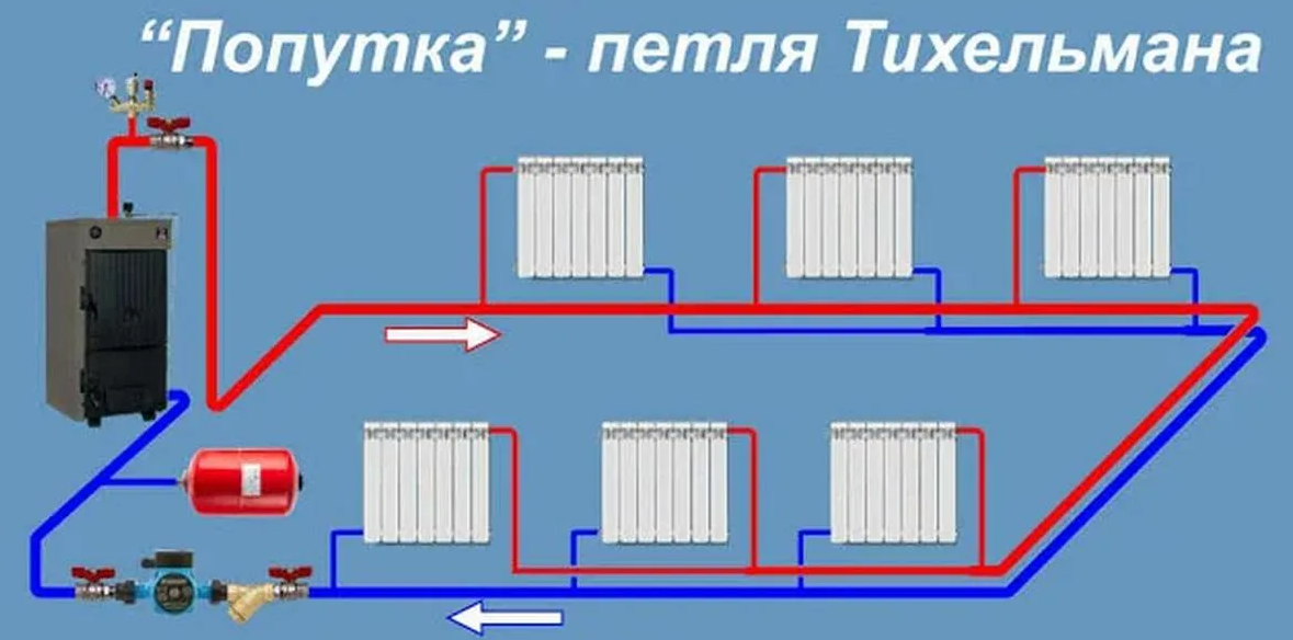
Rice. 14. Associated two-pipe horizontal radiator heating system of the “Tichelman loop” type. Such a system could work without a circulation pump if the boiler was lowered below the heating collector pipes into the basement or into a specially dug pit.
The use of natural gravitational draft to ensure circulation in the heating system did not allow the use of control valves in the system, since the available pressure at a small drop from the boiler in one-story houses gave extremely low driving pressure in the system, so that any additional resistance simply stopped circulation through the system.
Gravity draft is calculated based on the value of 120Pa per 1m difference in height from the boiler to the return manifold, which is equal to the difference in water density of 12kg/m3 at a temperature difference of 90/70C. (see Fig. 15)
977-965=12 kg/m3
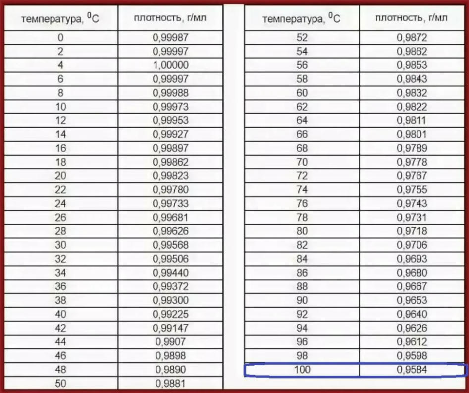
Fig. 15. Table of water density depending on temperature.
It was the low gravitational pressure from the boiler that made the “Tichelman loop” with openly laid thick horizontal collectors an almost no alternative solution in the private sector, where individual heating was used from solid fuel boilers (wood, coal) or from simple gas boilers (AGB) without additional circulation pumps .
The situation changed in the 1990s after the collapse of the USSR, when a stream of advanced heating systems poured in from the “decaying West” from abroad.
Thus, all the wonders of engineering from Europe became available to the private developer: wet-rotor circulation pumps of the UPS 25-60 type (Grundfos), thermostatic valves of the RTD-N type (Danfoss), plastic and metal-plastic pipes for hidden installation in the floor screed.
All these engineering miracles made it possible to get rid of bulky pipe collectors around the perimeter of the house, hiding thin tubes with coolant in grooves in the walls or in the floor screed.
The use of thin pipes sharply increased the hydraulic resistance of the system, so that in order to adjust the coolant flow rate through individual devices, it was necessary to create very significant resistances on individual radiators, which were provided through specially installed high-resistance valves of the RTD-N type (Danfoss).
Calculation criteria for two-pipe heating systems.
In the new reality, the weak gravitational draft from the boiler (50-100 Pa for a one-story house without a basement) no longer limits engineers in individual housing construction, giving them at their disposal previously unimaginable pressures of 20-50 kPa (2-5 m of water column) from small circulation pumps with a wet rotor and an electrical power of 25-70 W at flow rates up to 3 m3/h. (see Fig. 16-a-b)
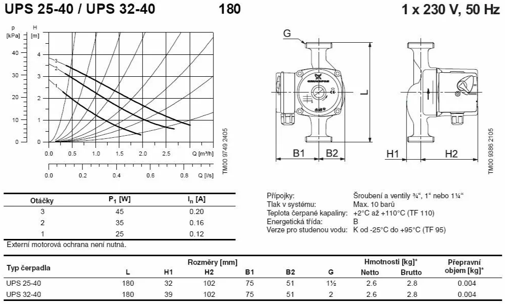
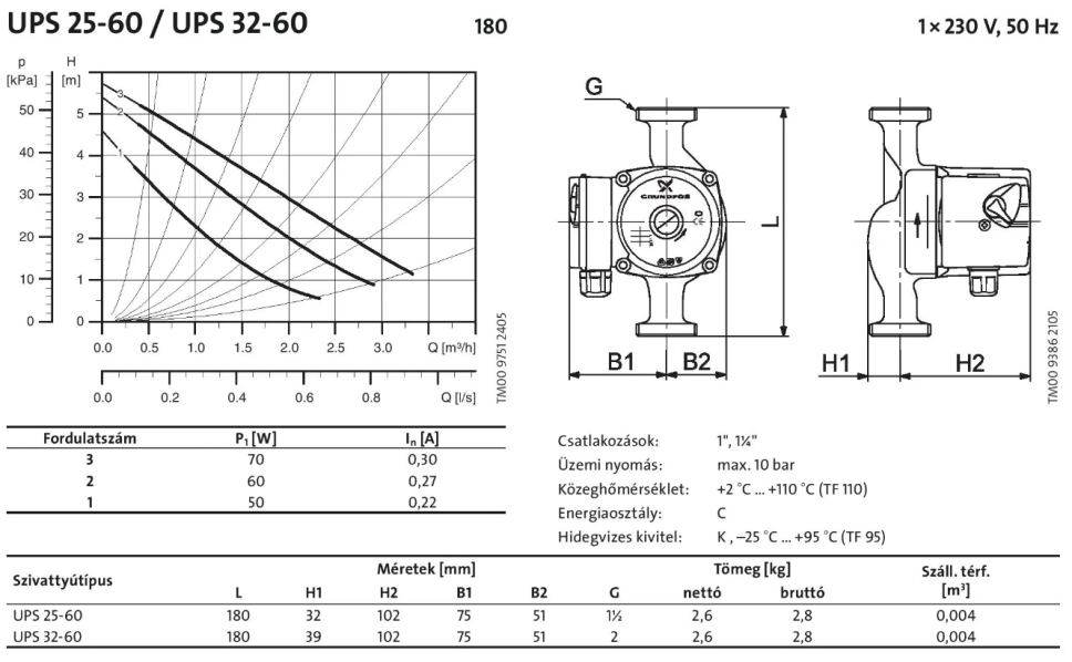
Rice. 16. Pages from the catalog of circulation pumps with a wet rotor (Grundfoss) with the characteristics of the most popular models in individual housing construction: A-UPS 25-40; B- UPS 25-60.
The available pressure increased sharply, and therefore the resistance of collectors in heating systems began to increase as their diameters decreased.
To equalize the costs of the radiators, it was necessary to sharply increase the resistance on their connections, for which they began to use special control valves with increased resistance, such as RTD-N DN 15 (Danfoss).
With the help of valves type RTD-N DN 15, it has become possible to provide very high resistances on the radiator at different coolant flow rates (see Fig. 17-18)
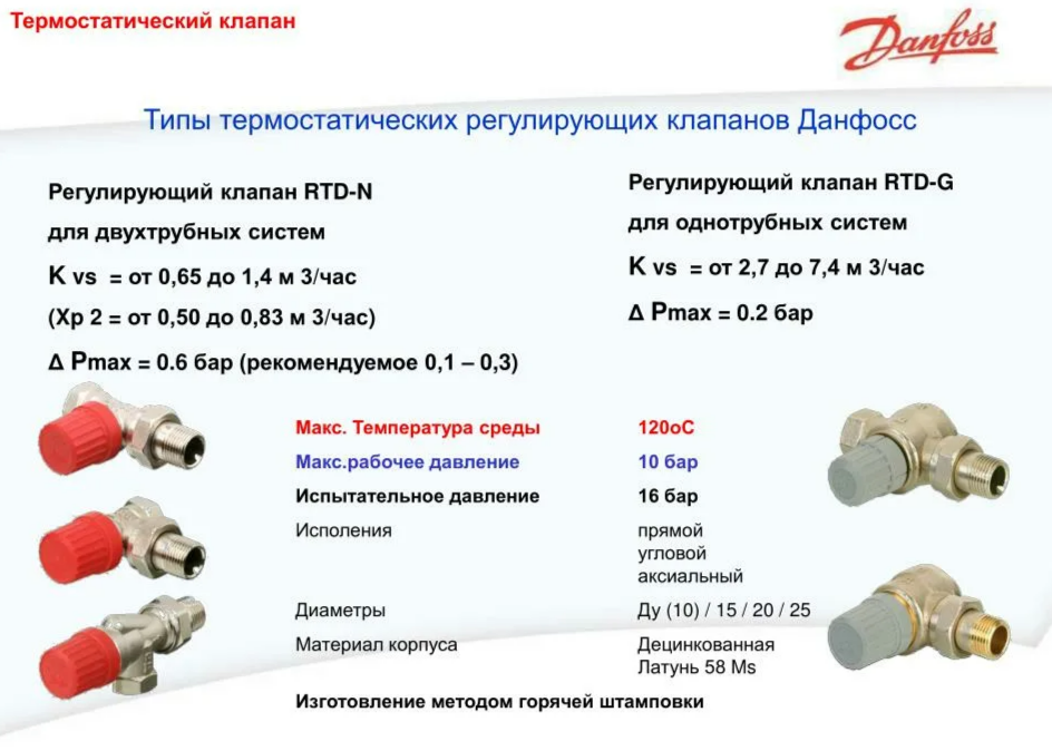
Fig. 17. Appearance of valves type RTD-N and RTD-G DN 15 (Danfoss). Valves of type RTD-G (right) are intended for use in single-pipe systems, as they have a very large flow capacity (Kvs = 2.7) which for DN15 at a flow rate of 42 l/h (1 kW at 90/70C) provides a resistance of only dP = (0.042/2.7)^2=0.00024 bar. = 24Pa.
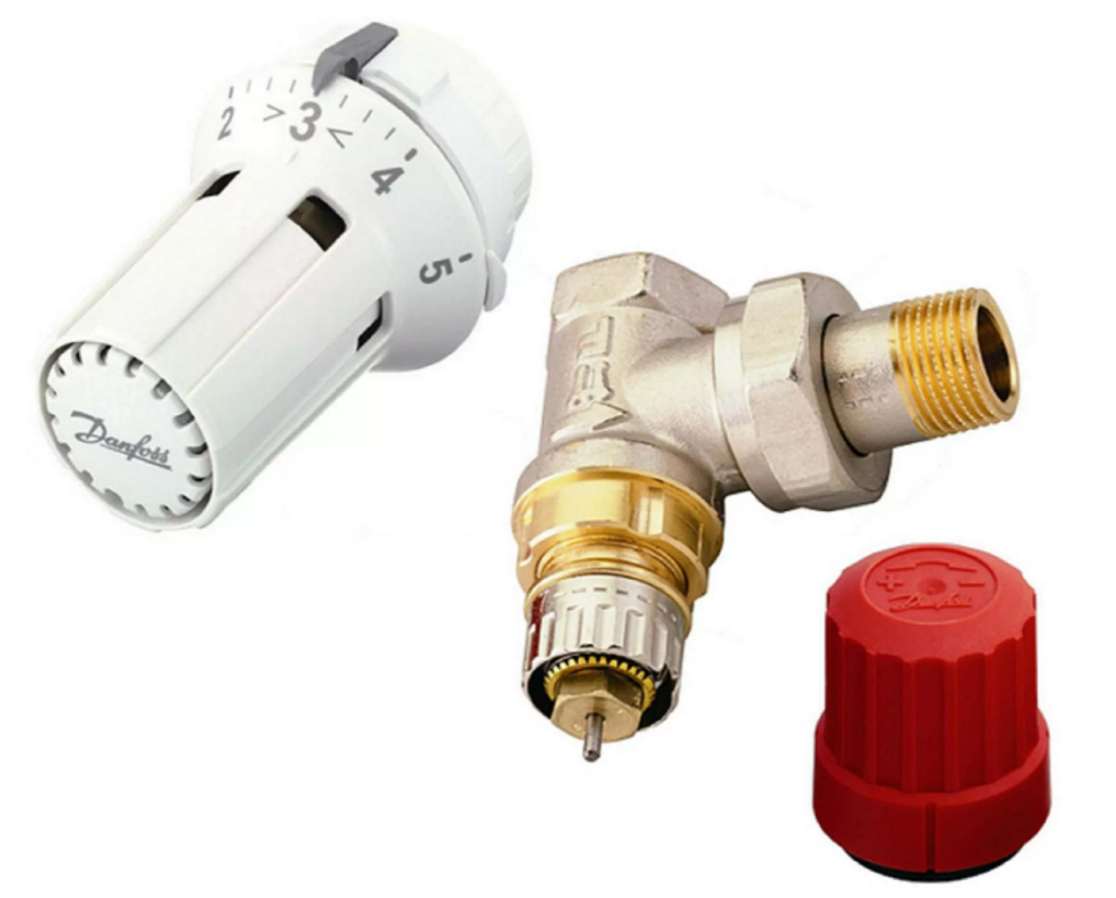
Fig. 18. Appearance of RTD-type valves DN 15 (Danfoss) and the thermostatic head for it. Elements for adjustment are visible on the valve body: a toothed rotating ring of the valve travel limiter and a scale with numbers on the external dial.
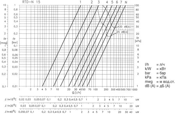
Fig. 19. Diagram of resistance of valve type RTD-N DN 15 (Danfoss) depending on the selected setting in the range 1-7-N. The dotted lines show the noise limits of valves with noise levels below 25 and 30dB(A), respectively.
A new limitation for the designer in pumping systems was the noise on the radiator control valves, the boundaries of which began to be specially marked on the graphs. (see Fig. 19)
Since the method of adjusting the flow rate remained unchanged (additional equal resistance of the radiators), the permissible resistances of the collectors of the heating system network increased proportionally to the increased resistance of the radiators.
According to the manufacturer’s recommendation, the resistance of the radiator valve should be 80% of the resistance of the entire system (80% priority).
If the pressure from a small pump in the individual housing construction was about 3 m.w.c., then only 0.6 m.w.c. remained for the collector resistance. (6 kPa), while there was almost never a risk of noise on the radiator valves.
The recommended radiator priority of 80% ensured accurate adjustment with hydraulic pressure discrepancy:
100/80=1.25
In this case, the flow discrepancy will be almost the same value as for the associated “Tichelman loop” with a DN40mm collector:
1.25^0.5=1.12 or +- 6%.
Currently, this recommendation from the catalog of the valve manufacturer (Danfoss) has found its way into the modern SP60-2020 “SNiP 41-01-2003 Heating, ventilation and air conditioning”, but in a more stringent form, namely:
The pressure loss discrepancy should not exceed 5% for passing pipelines and 15% for dead-end pipeline routings. (see Fig. 20).

Rice. 20. Fragment of the text SP60-2020. Under the header of the document at the top of the page, only one paragraph of clause 6.2.10 remains visible, but which tells extremely important information about the various conditions for the design and adjustment of heating systems for the associated (5% discrepancy) and dead-end circuit (15% discrepancy).
That is, SP60-2020 in clause 6.2.10. resolutely suppresses talk about the “wonderfulness” of the associated heating scheme, introducing for it a 3 times more stringent standard for the hydraulic discrepancy in the system. We calculated exactly this 2.8-fold discrepancy difference between the hitchhiker and the dead-end circuit at the beginning of this article.
That is, according to SP60-2020, in a passing lane you need to provide 95% of the priority on the device, and in a dead-end only 85% of the priority on the device.
Thus, the authors of SP60-2020, by differentiating the standard for hydraulic discrepancy in dead-end and associated systems, have normatively stopped attempts to narrow the diameters of the collector parts for associated systems. So now designers are forced to carefully consider the hydraulics of the heating system without reference to the “magic of self-balancing” of the Tichelman loop.
Negative properties of two-pipe heating systems with high-resistance valves type RTD-N DN 15
Previously, the diameter of the local narrowing was calculated F6mm, which provided a radiator resistance of 100 Pa.
Now the question arises:
What narrowing diameter is needed to obtain dP = 30 kPa (3 m.water column) on the same radiator?
The answer is quite simple:
A velocity head pressure of 30kPa is provided at speed
V=7.7m/s
Which at a flow rate of 42 l/h gives a diameter D = 1.4 mm.
There is only one question:
How does such a thin hole (Ø1.4mm) not become clogged with dirt and rust from the heating system?
The answer is obvious:
The tiny gap in the thermostatic valve of increased resistance in a two-pipe heating system regularly becomes clogged, which leads to the flow stopping and the radiator cooling.
In severe cases of blockage, even opening the valve to a higher flow rate does not help, and as a result, you have to dismantle the radiator and mechanically clean the clogged passages of the valve.
This problem occurs even in expensive cottages, where it would seem that there should be no dirt in closed heating systems.
At the same time, in a huge number of apartment buildings, single-pipe vertical heating systems do not have such problems with clogging for many decades in a row, but only if there are no thermostatic valves and narrowings on the connections to the radiators.
So in my 9-story panel house, a vertical single-pipe with an accordion convector has been working without repair for 45 years in a row.
Are there any prospects for hitchhiking at the moment?
In high-rise housing construction, vertical riser two-pipe systems are practically impossible to use.
To implement two-pipe heat supply to apartments, horizontal distributions are now used from floor-to-floor manifold cabinets with automatic constant flow valves at the outlets from access heat supply risers to apartment-by-apartment distribution manifolds.
This solution eliminates many problems with transit risers through the uncontrolled area of a private apartment, but creates a bunch of other problems, as was written about in the previous article on this topic (see link)
https://habr.com/ru/articles/727472/
What about low-rise construction and individual housing construction?
Earlier in the article, we found out that the resistance of two-pipe systems increases in proportion to the cube of the length at a constant specific heating power along the length of the collector.
It turns out that the longer the branch of a two-pipe system (of any configuration), the thicker the cross-section of the collector needs to be made.
At some point, it turns out that the collector pipes are so thick that the heat transfer from them blocks the power of the radiators.
At this point, the two-pipe heating system turns into a register heating system, where separate radiators are no longer needed.
Well, it is most advantageous to design a register heating system with a through flow of coolant in a bifilar layout of heating pipes. (See Fig. 21.)
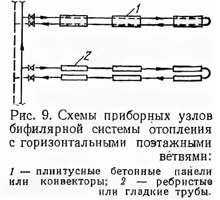
Rice. 21. Picture from a textbook with diagrams of bifilar horizontal heating systems.
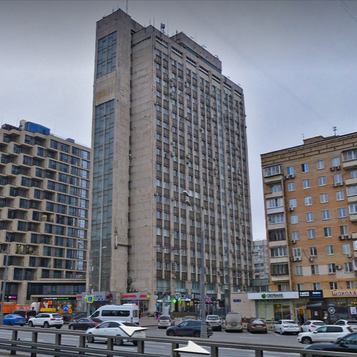
Fig.22. This high-rise building has bifilar horizontal heating systems with metal convectors made of aluminum sections (type 1). Previously, this was the building of the Soviet research institute in Moscow on Mira Avenue, building 95. In this building I I somehow worked myself (I spent the winter of 2020/21) and I had no complaints about the heating.
It is easy to calculate that a power of 1 kW over a length of 3 linear meters of a facade for a heating system is heat loss in a private house with continuous facade glazing or with walls made of 150 mm timber, that is, a house with very low energy efficiency.
For a one-story house 15x10m made of aerated concrete D400-400mm with normal glazing, one 2×1.5m window every 3 m of the facade (33% glazing) will have nominal heat losses in the Moscow region at the level of the total:
N=(100/3+50/0.7+150/4+150/4)*50= 8988 W= 9 kW.
That is, a real modern house will have heat loss of only 56% of our initial assumption, where there were 16 radiators of 1 kW each, which gave a total of 16 kW.
For a register of 2 parallel pipes, 1 kW of heat transfer on the 90/70-20C graph is provided with the heat transfer area of the register:
S=1000/(8.9*(80-20)*2*3)= 0.312 sq.m./m.p.
This corresponds to a pipe with an outer diameter of Ф100mm.
For a power of 570 W for every 3 m of facade in a modern insulated house, registers also made of two pipes, but with a diameter of only Ф57 mm, will be sufficient.
That is, laying two pipes (back and forth) with a diameter of Ф100mm or Ф57mm along the external walls under the window sills makes it possible to uniformly heat the house without radiators at all.
Hydraulic calculation of bifilar register.
For a house with a perimeter of 50 m, only 100 m.p. will be required. steel pipe Ф100mm.
The pipe Ф102×3 mm (DN90mm) with a flow rate of 7.2 m3/h has a resistance of only 11 Pa/m,
Which at a flow rate of 0.7 m3/h (16 kW with a schedule of 90/70-20C) will give a resistivity of 0.11 Pa/m and a total system resistance of 100 * 0.11 = 11 Pa.
That is, the resistance of the pipe heating system is so low even within the framework of the minimum gravitational draft of 50Pa that one can consider replacing two F100 pipes with four parallel pipes F51x3mm (DN40).
For an insulated house with heat loss of 9 kW and a register made of pipe Ф 57 mm (DN50) at a flow rate of 0.4 m3/h (9 kW with a schedule of 90/70-20 C) will give a resistivity of 0.6 Pa/m and a total system resistance of 100 * 0, 6=60Pa. Which also fits into the gravitational pressure of the boiler with a difference of 50 cm.
Optimization of the Ф100mm register for 2 Ф50mm registers
Two registers with a diameter of Ф100mm are a very bulky pipe in the interior of a house.
It is also much heavier due to the large volume of water in it. When saving weight, it may be necessary to lay several passes of a thinner pipe instead of one pass of a thick one. But while maintaining the same area of the heat-transferring surface of the pipe.
In the private sector of individual housing construction, the aesthetics of registers and the space they occupy are more important.
So it is aesthetically more advantageous to have 4 rows of pipes with a diameter of Ф51mm (DN40) under the windows with a pitch of 100mm under a window sill with a height of 700mm (the height of a desk) than two thick registers with a diameter of Ф102mm.
A pipe of DN 40 with a flow rate of 720 l/h has a resistivity of 9 Pa/m.p., which over a length of 4×50 = 200 m will give a resistance of 9 * 200 = 1800 Pa (180 mm water column).
The pressure of 1800Pa is much higher than the available pressure of 360Pa of gravity draft, even with a difference of 3 m to the boiler room in the basement.
That is, when the diameters are reduced by 2 times, the resistance increases so many times that it is also necessary to change the length of the pipe.
Changing the length by 2 times will reduce the system resistance by 8 times to 1800/8=225 Pa.
The register resistance is 225Pa – this is also excessively high for gravitational traction, so you will have to use pipes Ф57mm (DN50) instead of Ф51mm (DN40).
We have already given the calculation of a 100m pipe for DN50mm above.
Total for registered heating systems:
In a private house, to reduce the cost of the heating system and increase its reliability, registers made of smooth pipes of constant diameter can be used instead of a rather complex heating system with separate radiators and pipes of different diameters. So in a one-story house 10×15 = 150 square meters. it is enough to weld a register system from a diameter 100mm pipe (or two systems from a diameter 57mm pipe) each 100 m long.
In this case, ideal balancing of the system in terms of heat transfer will be obtained due to the equality of the total return of two adjacent pairs of pipes in temperature.
Similar solutions with long registers made of smooth pipes (but with pumping) are also excellent for long one-story buildings (warehouses, greenhouses, cowsheds, army barracks) or for large rooms with continuous belt glazing (old Soviet administrative buildings).
It is worth noting that register systems have higher strength (vandal resistance) and are easier to clean, which is especially important in the army and in agriculture.
In addition, such register systems will be cheaper, more stable in operation and more reliable (than radiator systems), due to the absence of expensive radiators and balancing fittings for them.
Comparison of the cost of radiator and register heating systems for a private house of 150 square meters.
The cheapest flat panel radiator for 1 kW (Type 22-500x500mm) with two ball valves (400 rubles each) and one balancing thermostatic valve (1500 rubles) will cost at least 6.5 thousand rubles. (see Fig. 23-25)

Rice. 23. Current retail prices for a 1 kW panel steel radiator.

Fig.24. Current retail prices for thermostatic valve of increased resistance type RTD-N Du15.
At the same time, 6 linear meters of F100mm pipe will cost 2 times less, that is, only 3150 rubles from the price calculation of 525 rubles/m.p. The same situation is with the price of pipes Ф48-57mm (see Fig. 25-26).
That is, the pipes will cost 2 times less than radiators, and this does not take into account the fact that in addition to the radiators themselves, you will also need to additionally buy pipes for DN40 manifolds at half the cost of the registers.
True, the steel pipe will still need to be painted, which also costs money.
But the collectors for the radiators will also have to be painted, albeit in 2 times less quantity.
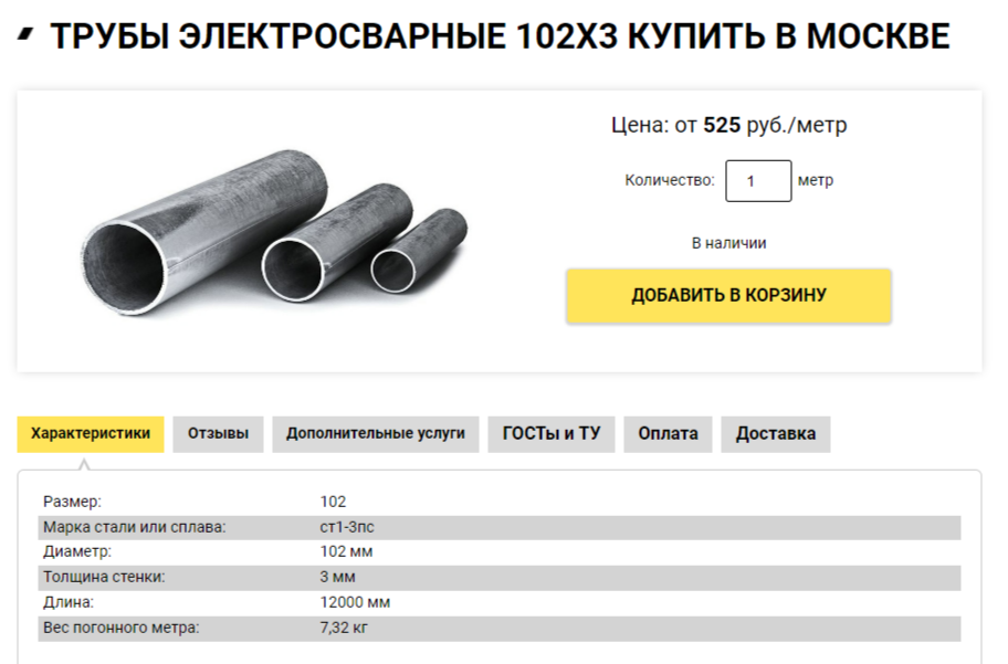
Fig.25. Current retail prices for steel pipes for heating registers Ф102mm.

Fig.26. Current retail prices for steel pipes for heating registers or two-pipe radiator manifolds.

