Replacing the motor on the LifeSpan Fitness TR5000 treadmill
A somewhat extraordinary note… Since Corona, I have been working at home on a tabletop. When I was looking for something to buy, I came across a small local store FitOffice, where the choice was TR1200 or TR5000. According to reviews, both are good, but one requires regular lubrication and requires use for several hours a day – while the second does not require lubrication and is suitable for walking all day long. My wife insisted on the second one 🙂
In short, over 4 years of use, I only put about 10 thousand km on it, but it started make a lot of noise — according to phone measurements, more than 60 dB at 5 km/h, and even with a terrible high-frequency component, which made the noise even worse. Well, that is, I could work behind her (the table shielded me from direct noise), but the noise next to her became disgusting.
The official caliper told me by mail “this is normal” – and FitOffice said that it looks like a problem with the motor – someone on reddit said the same thing, and to my ears it sounded like a problem with one of the bearings. As a simple measure, I was offered to change the motor brushes, these instructions I found (caution: video). But the brushes turned out to be almost unused (less than 1mm was eaten), and the replacement did not affect the sound. The only option left is to replace the motor.
Considering that the track was already under warranty, and the replacement itself looked like a simple matter, I decided to change it myself, although I did not find any instructions. So now I'm filling this vacuum 🙂
Please note: I am a big programmer and should not be able to change motors. Well, that is, I can replace the motor in the track, but not because I’m a programmer. If you decide to do something according to the instructions, do it at your own peril and risk and act according to the circumstances! I am not a master and this instruction is not official at all.
What you need
To replace the motor in the track you will need:
Track TR5000
New compatible motor
crosshead screwdriver
Open-end wrenches for 12, 13 and 14
8 wrench
Short hexagon 6 – the one that comes with the track itself is too long, so I used a screwdriver bit + open-end wrench 6
Work gloves (you can get a little dirty there)
Something reliable to lift and fix the path 10cm above the ground (I lifted it with my hands and feet, but 8-10cm blocks of wood can help)
A phone to take a photo of what it looked like before work began – so that you know how to put everything back later.
Opening
Before opening the track, it should be DISCONNECTED.
Check that everything is de-energized and all cables are disconnected from it.
You should roll out the track from under the table.
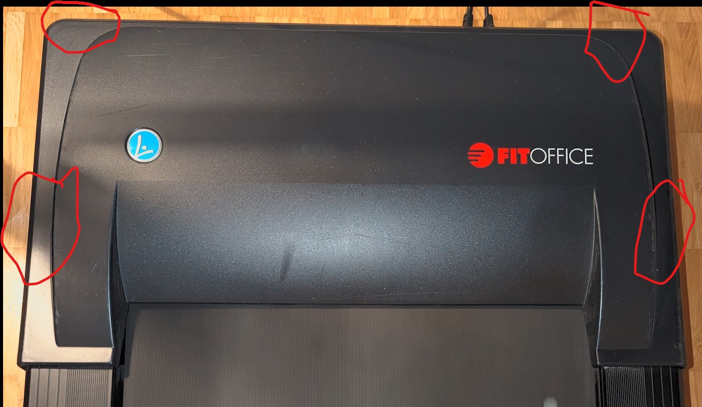
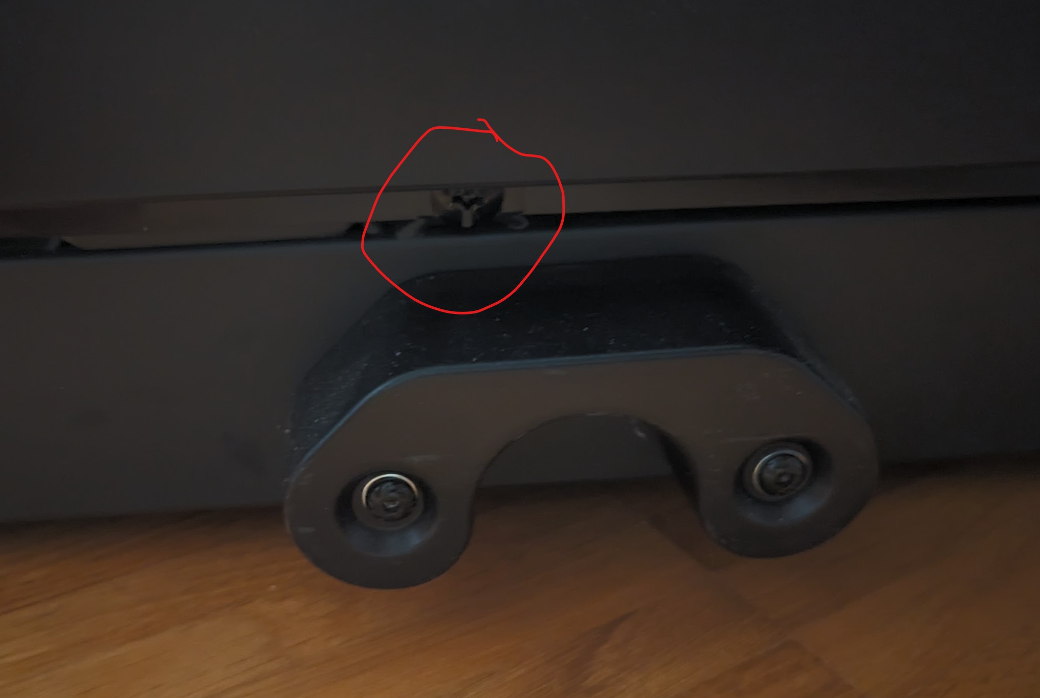
Inside the track, when viewed from its front, there are:
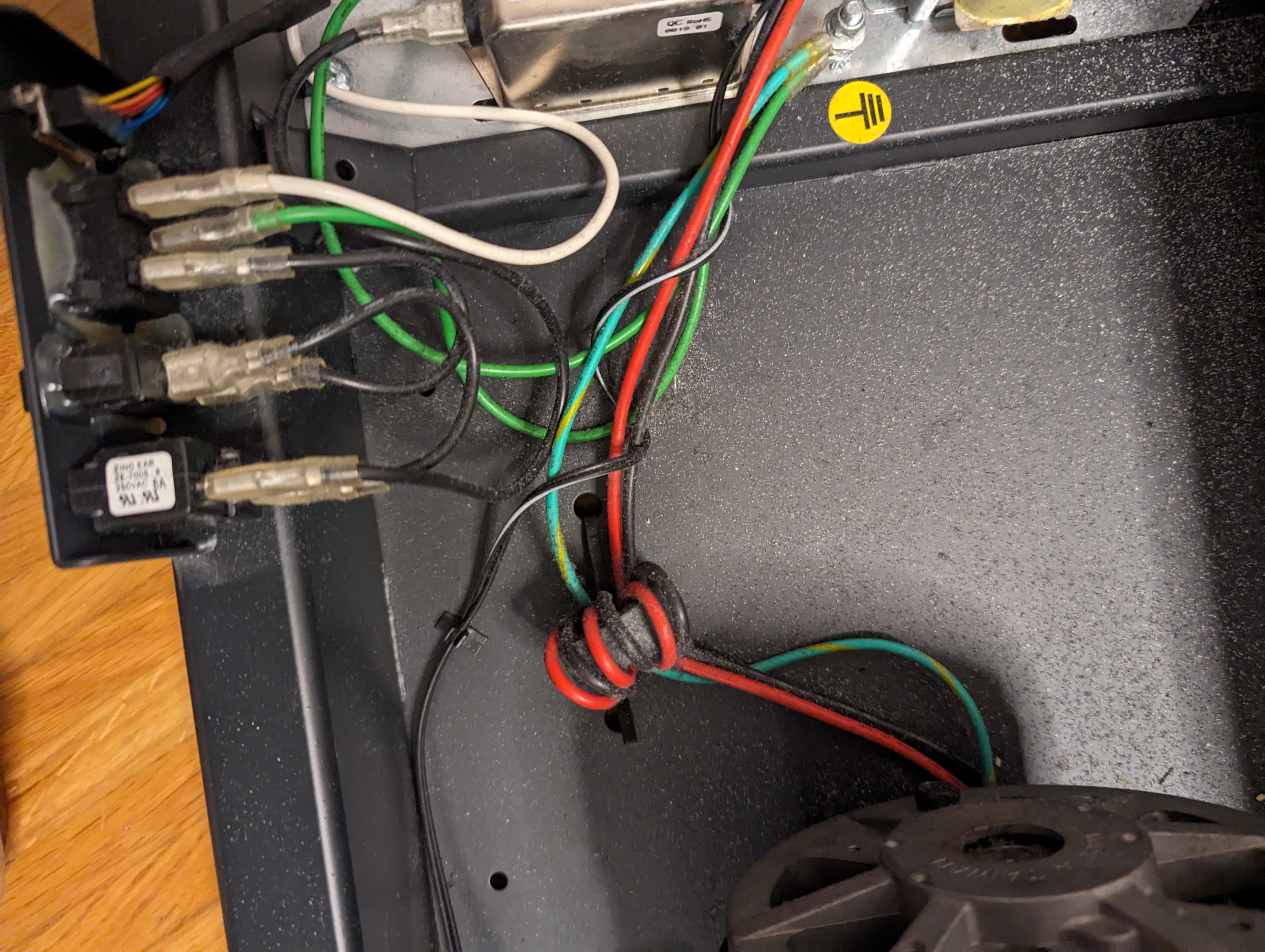
Left: control electronics. The motor is connected by connectors at the ends of the thick red (plus) and black (minus) wires, plus the blue-green wire is screwed to the ground bolt.
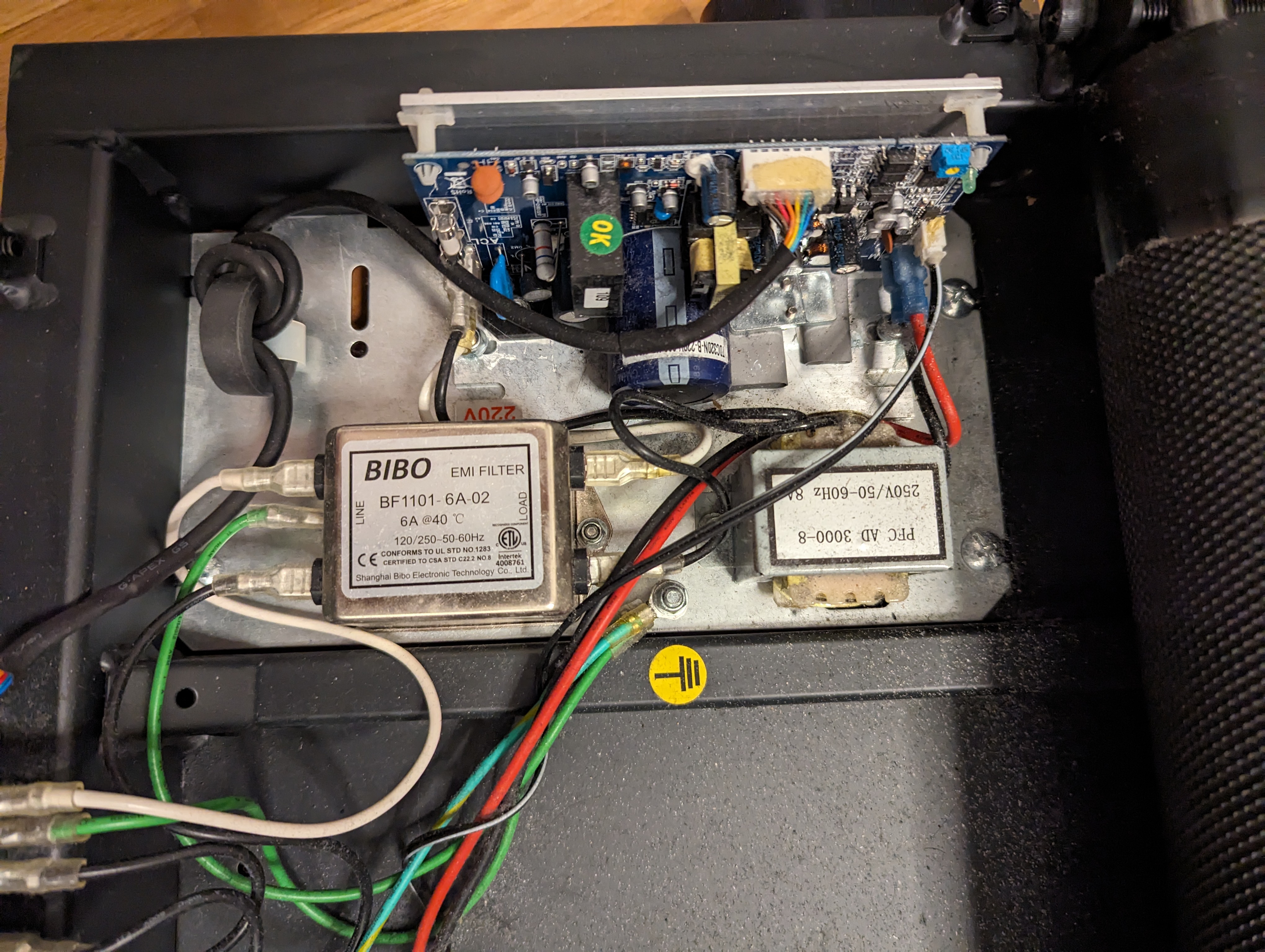
There is a large ferrite ring in the middle. Let's pay attention to how the wires go: the ground goes straight through it, and the power makes three turns.
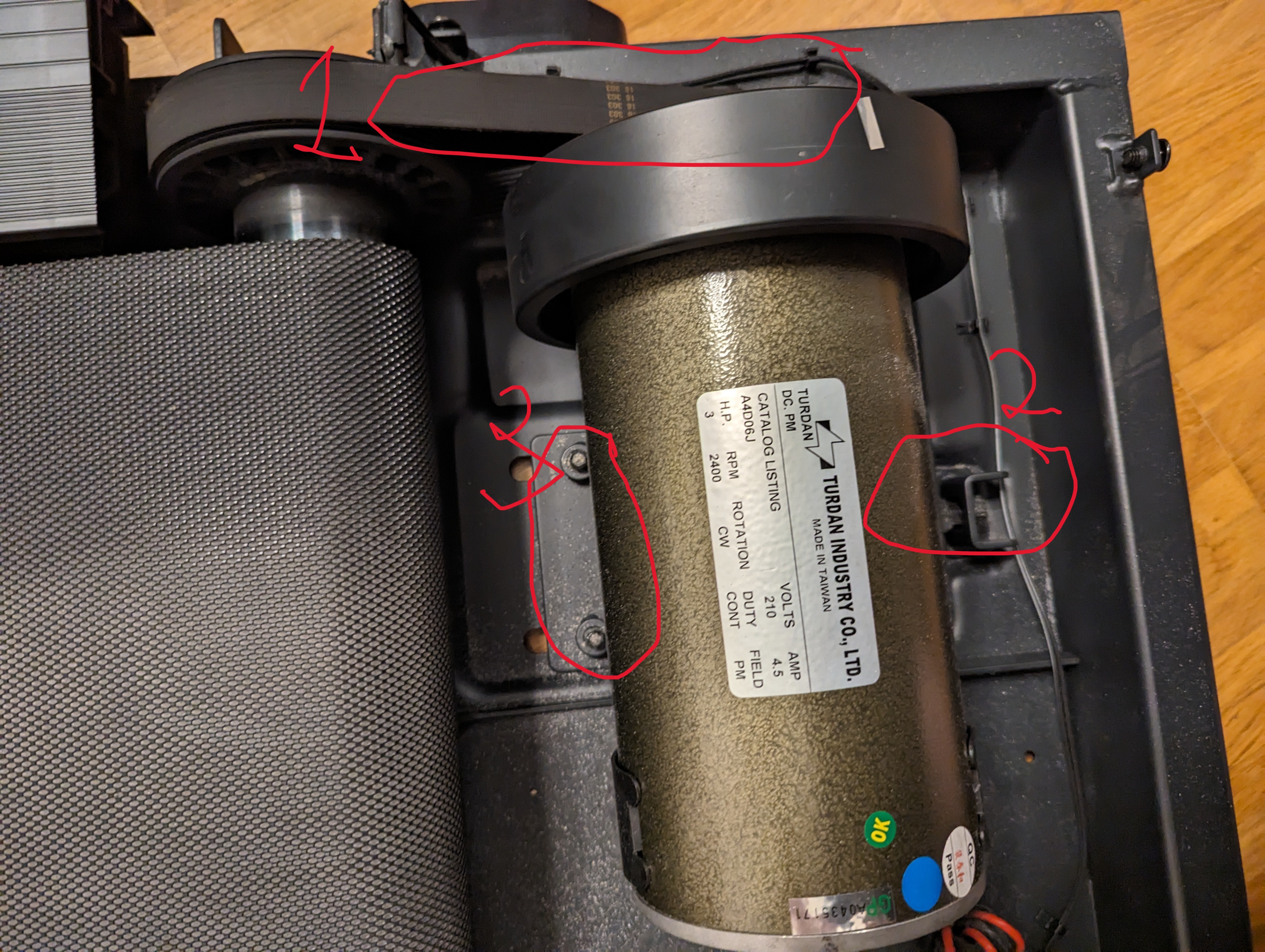
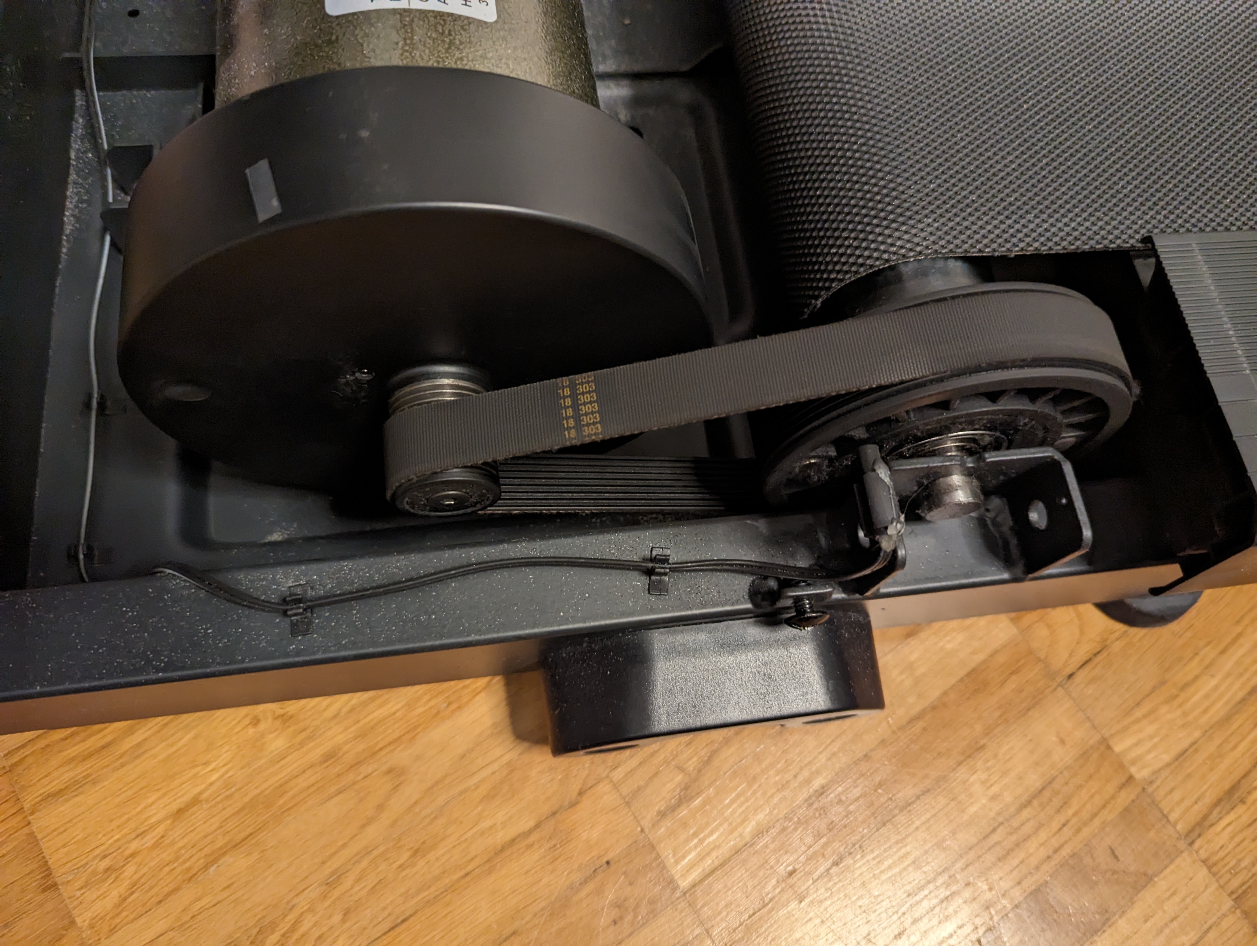
Firstly, the tension of the transmission belt in zone (1). You should press with your finger to remember approximately how much you will need to tighten at the end.
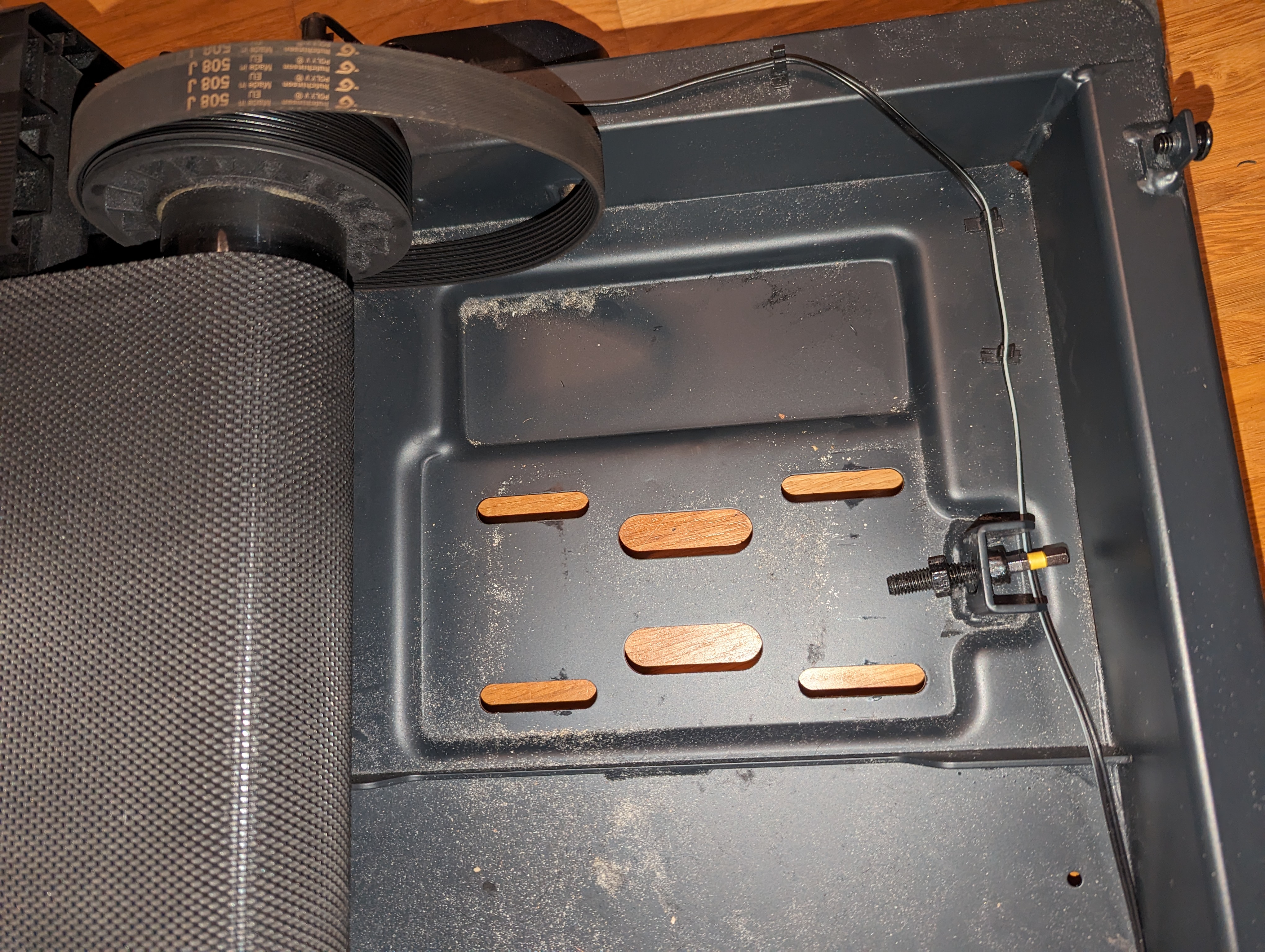
The tension system is organized in zone (2). It consists of a flat nut (a), which is held in a groove in the metal, a bolt with a hex head (b) (and yes, there is not enough space here, you need a short hex 6), plus it is clamped so that it does not come loose with a nut (c) after it is tightened how to.

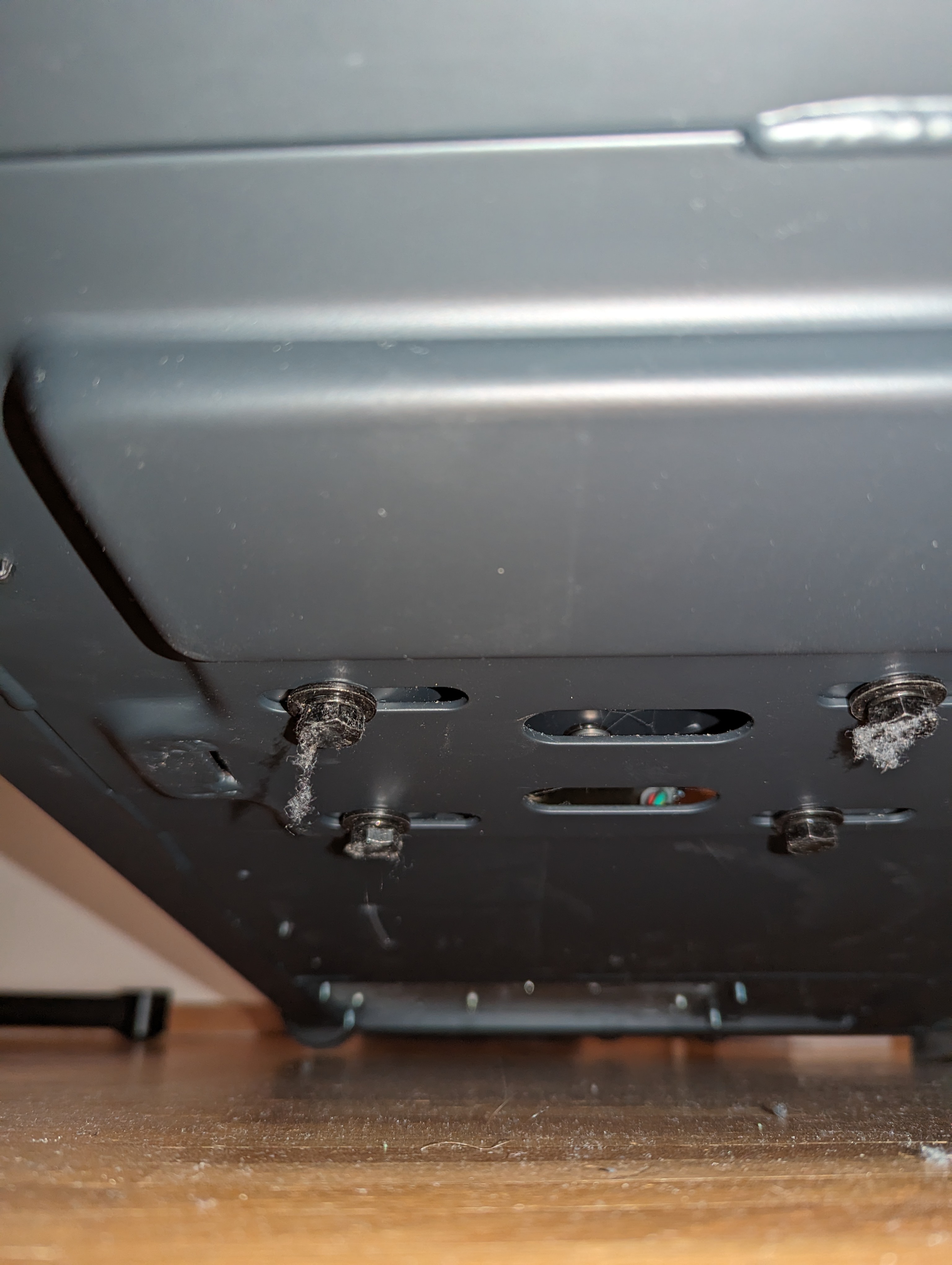
The motor is screwed to a metal base, which in turn is located in long holes (3), that is, the motor can move back and forth so that the belt can be tensioned as necessary. Of course, these 4 bolts are screwed from underneath the track for ease of maintenance.
Removing the motor
Motor removal procedure:
Turn off the track.
Make sure the track is turned off and all wires are disconnected from it.
Loosen the lock nut (c) in the tension system, then rotate the tension bolt (b) to remove the nut (a) completely.
Unscrew the 4 bolts that hold the motor. To do this, the path must be raised 8-10cm so that a hand with a key can fit there. I raised the track on the side legs to the maximum that they allow, and then folded it onto my left hand to lift it and supported it with my foot, and twisted it with my right, but it may be more convenient to take large wooden blocks 10cm high and put them in the corners of the track – the main thing is to fix it so that the path could not jump off them and fall with all 50 kilograms on their hands!
Disconnect the wires from the motor: pull out the black and red ones from the board, pull them out of the ferrite and unscrew the ground (the motor is on the top, so it’s easy to remove).
Now you can safely remove the motor
The metal plate on which the motor rests is screwed to the motor with two hex bolts – unscrew it from the motor.

We install a new motor
We assemble in almost reverse order:
We screw the plate to the new motor (watch the orientation of the plate!)
We put the motor in its place, and put the 4 bolts back – but do not tighten them
We place the belt on the motor axis and center it on the axis on the roller
We put back the flat nut (a) and tighten it with the bolt (b) until we get the required belt tension (do you remember what it should be? not too weak and do not overtighten)
Now you can tighten all 4 bolts tightly – and check the tension again.
(If you put something under the path, you can now remove it).
Tighten the locknut (c) in the tension system.
We stretch the blue-green wire from the motor through the ferrite and screw it onto the grounding bolt.
We stretch the power wires, making three turns on the ring, and connect them to the board in the same places as before. I have black at the bottom (on the board “-“) and red at the top (plus is written on the board).
We turn the track itself by hand – the motor should rotate easily and should not make any extraneous sounds.
Put the cover back in place and tighten the bolts around the perimeter. Before tightening the side bolts, slightly lift the cover above the track so that the cover does not scratch by the tape, otherwise strange sounds will again occur.
Enjoy!
After replacing the motor, the noise dropped from 63 dB when it rotates at 5 km/h idling to 52 dB. Divine!
I hope to continue enjoying it now for at least another 5 years 🙂
