Pulse (Re)Magnetizer for neodymium
Neodymium magnets come in different types. Not only in shape and size, but also in the orientation and configuration of the magnetization itself. Even simple shapes like a cylinder can be magnetized both along and across (or some kind of goat magnet, if someone needs it). Here is a picture, honestly downloaded from the manufacturer from Google:
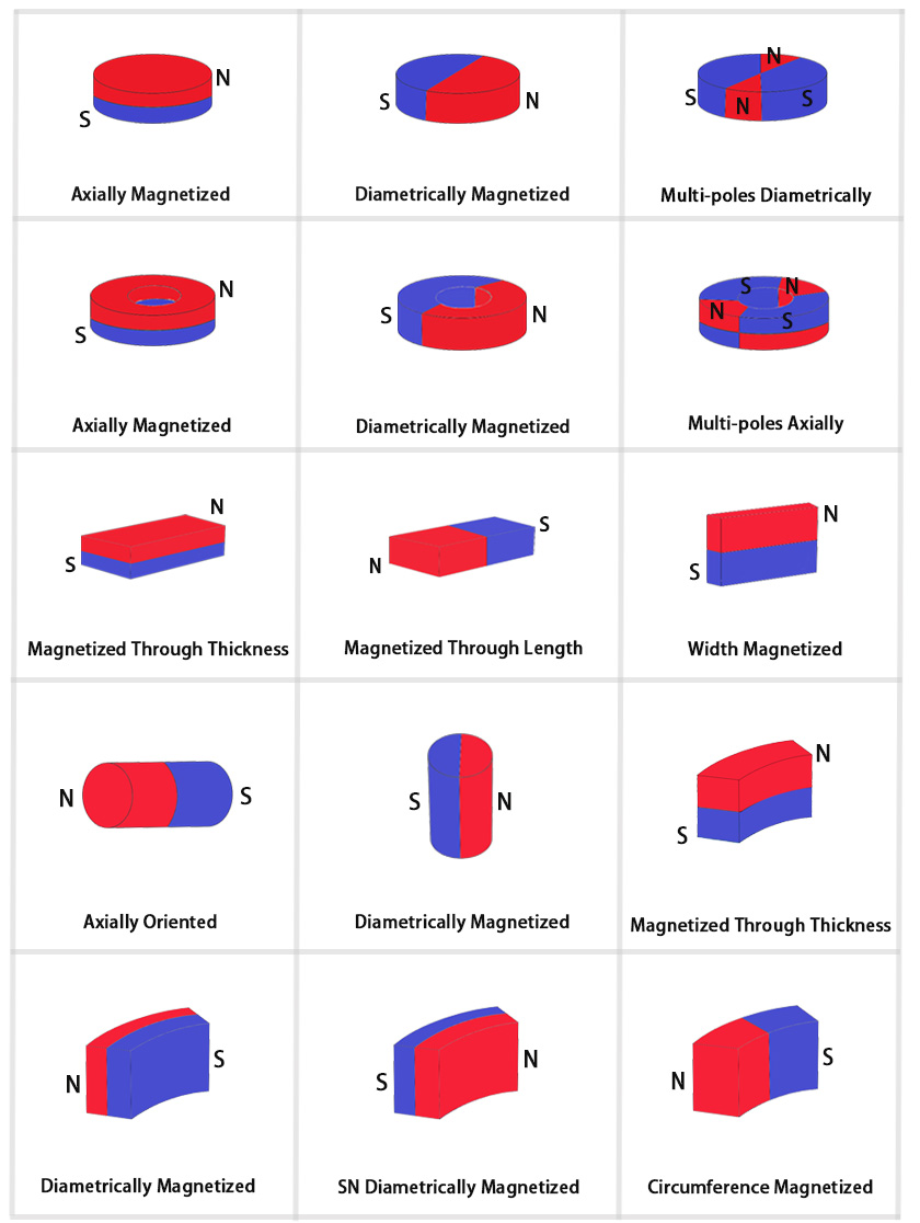
This is all good, but what does it matter to us distributors – whatever orientation the magnet was made at the factory – that’s how it will be, just order the ones you need, right? Yes, but I have a bucket of tin magnets! Maybe they can also be used for something interesting?

These magnets have one feature – their halves are magnetized in opposite directions. Sometimes this is even convenient, but for some applications they are completely unsuitable in this form.

I had several such applications in mind (you can wait for the translation of the next article or check it out on Medium now), and I began to think about creating my own magnetization apparatus. In theory, everything looks simple: the workpiece needs to be immersed in an external magnetic field, oriented in the desired direction, and at the same time strong enough to “turn over” the magnetic domains. In practice, the difficulty is that for NdFeB this “strong enough” lies somewhere in the 2 Tesla region. There are not many practical ways to create such fields, but the simplest is, of course, an electromagnet. Typically, electromagnets (such as those that hold entrance doors, for example) do not consume that much power. But that's only because the iron core with its large, thick μ does most of the heavy lifting. However, iron stops working well and its μ drops significantly for fields above 1T. And there are also some other problems with the option of using the core. So we are left with an “air coil” in which the entire field is created solely by the current in the winding. The magnitude of this current to achieve the desired field strength is determined by the geometry of the coil. For magnets made of tin, we need a solenoid with a diameter of ~50mm and approximately the same length. Sprinkling the problem with a number of formulas, which I will leave for another article, we find that we need to pass a current of the order of 10 kA through 20 turns of the coil. No, this is not the total current of all turns, but the current in each of them. No, you didn’t think so, 10kA is really quite a lot. In your apartment you probably have 25A circuit breakers, for comparison. And if we do not want the coil to be disposable, we will have to greatly limit the time for such currents to pass through it. In our case, a time of 1/1000 of a second would be quite appropriate for the task.
But the technical requirements don't end there. If the only question was the magnitude of the current, then something like a resistance welding machine would solve the problem. But by creating a field around the coil, we are also dealing with the energy of this field, which needs to be pumped through the coil. Here we are talking about values of the order of 1000 J. Not that this is very much, but it means that with a current of 10 kA, a voltage of 100 V is needed to fill 1000 J in 1 ms. And if you add some missing coefficients, losses and other nuances, it will come out more like 500V. And 500V x 10kA is already 5MW, for a second. Not great, not terrible, as they say, but on the scale of a rural substation.
Perhaps such figures would force a timid engineer to abandon the idea, but objectively there is nothing very cosmic here. Let's start with the energy storage device. An electrolytic capacitor 470uF x 400V can be filled with 38J. 9 pieces of these already give 340J and here they are:

It would be possible to connect them with a “snake” onto a common thick bus, but there are difficulties associated with the uniform distribution of current between the individual capacitors. It's easier to cut pieces of wire of equal length to each of the capacitors and lay them out, trying to create some star-shaped symmetry. Now we need 4 such blocks to achieve 1400J in total.

It is convenient to assemble the blocks into a stack using racks of threaded rods, generously flavored with nuts.

The second critical component will help us quickly connect charged capacitors to a coil in a 5-megawatt pulse. For this we will takeYa little thyristor. This particular one can handle 250A on average and 6kA per pulse (but in fact, a little more too, if the pulse is short).

Let's connect all this equipment with busbars made of thick copper foil and add a “flyback” diode in parallel with the coil.

Four capacitor banks are connected in parallel-series 2×2 to achieve a total voltage of 800V. With proper matching with the coil, by increasing the operating voltage we can reduce the switched current, thereby facilitating the operation of the thyristor.
Now you need to add capacitor charging circuits and thyristor control. During the experiments I had several variations of the scheme, but the general idea is something like this:

The capacitors here are charged using a voltage multiplier directly from the network (!! VERY DANGEROUS!!). The thyristor is triggered by a button from a separate lithium battery. When working with such a circuit, you need to remember that during charging (switch SW1 is closed) all components of the circuit, including the coil, have a galvanic connection with the network!
The voltage multiplier is assembled on diodes D1-D4 and high-voltage film capacitors C1, C2. A 60W incandescent lamp LA1 is connected in series to limit the charging current. Suppressor diodes D7, D8 are a primitive means of equalizing the charge voltages on the two halves of the capacitor block. To monitor how equal these two voltages are, use a Balance voltmeter. Flyback diode D10 prevents polarity reversal of the storage electrolytes in the second quarter of the oscillation cycle in the LC circuit. The discharge button SW2 supplies a short unlocking pulse to the thyristor through capacitor C5 (a pair of microfarads). I’ll also add that in my actually tested implementation, the zero contact SW1:2 was connected to the middle point of the drive to ensure symmetry of the multiplier operation. But then the potentials on the thyristor control circuit can be even more unsafe. In general, the Q&D solution still requires improvement.
Now, briefly, for about forty seconds, a review of what came out in one of the intermediate implementations.
To demonstrate, I heated a piece of HDD magnet on gas to the curie temperature and complete loss human species magnetization. Then I placed this blank inside the coil:

Now we charge the electrolytes:
And now… Fire!
Yes, NdFeB was successfully magnetized! However, I was not sure that the magnetization was complete at these parameters and decided to try a discharge with a maximum operating voltage of 800V. This turned out to be enough not only to completely saturate the magnetic material, but also gave unexpected acceleration to metal objects thrown nearby. In addition, the coil itself was damaged:


In general, the result was encouraging, but now I needed to redesign the coil to achieve greater mechanical strength, which is described in a separate article. You can wait for it to be translated, or go to Medium right now.
Link to original of this article on Medium.