How to transfer a shader from a game engine to Substance Painter

Unity shader
The game uses matcap shading. In addition to the usual diff texture, two pre-created Matcap textures are also transferred to the shader. They are interpolated and blurred using two masks, respectively. As a result, the Matcap texture is multiplied by diffuse and fake glare and reflections can be seen on the material.

The example below shows how Matcap is implemented in a shader graph. In this case, two Matcap textures are packed into one and divided into channels. That is, metal and non-metal in the channels R and G, respectively.

Two Matcaps are interpolated for an example by checker.
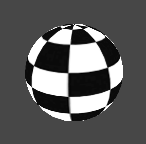
The result is a certain analogy with metal and non-metal as in PBR shading.
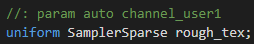
We wanted to add roughness and dirt to the materials, to create some kind of roughness analog in PBR shading. To do this, we used the texturing method. mip-mapping. A sequence of textures creates the so-called MIP pyramid with a resolution of maximum to 1×1. For example: 1 × 1, 2 × 2, 4 × 4, 8 × 8, 16 × 16, 32 × 32, 64 × 64, 128 × 128. Each of these textures is called a MIP level. To implement scuffs in the shader pixel by pixel, based on the mask, you need to select the required MIP level. It turns out like this: where the pixel on the mask is black, the maximum MIP level is selected on Matcap’s, and where the pixel color is white, the MIP level is 0.
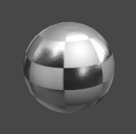
As a result, the shader makes it possible to simulate reflections and highlights, add light roughness and scuff. And all this without the use of Cubemap, without complex lighting calculations and other techniques that significantly reduce the performance of mobile devices.
Setting up Substance Painter to create a shader
All available shaders in Substance Painter are written in GLSL.
Specifically, to write a shader for Substance Painter, I use the free VS Code. For syntax highlighting, it is better to use the Shader languages support for VS Code extension.
There is very little material about the API in Substance Painter, so the standard documentation that can be found in Help / Documentation / Shader APIis just priceless.

The second thing that will help in writing the shader is the standard shaders in Substance Painter. To find them, go to …/ Allegorithmic / SubstancePainter / resources / shelf / allegorithmic / shaders.
Let’s try to write the simplest unlit shader that will show Base color. First, create a text file with the extension .glsl and write such a simple shader. Perhaps, while nothing is clear, I will tell in more detail about the structure of the shader in Substance Painter further.

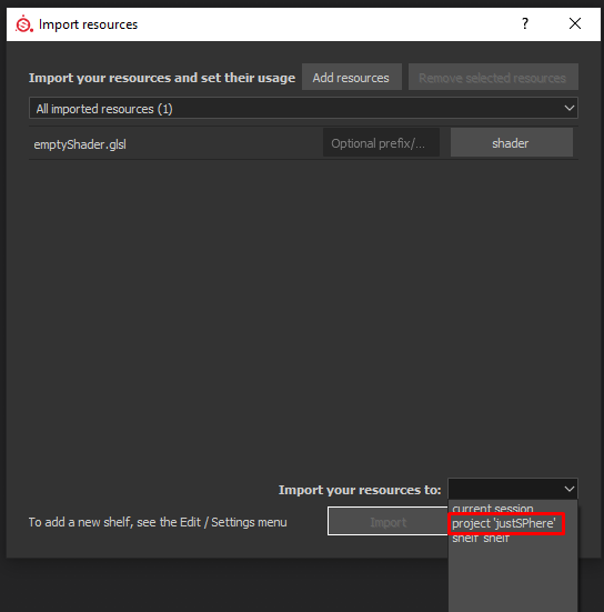
Create a new project and drag the shader onto your shell. In the drop down list Import your resources to select project ’Project_name’.
This is necessary so that all changes can be updated.
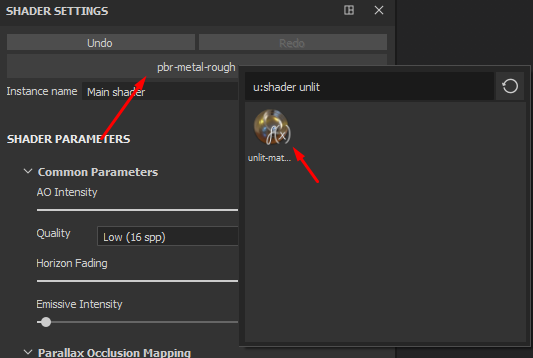
Now go to Window / Views / Shader Settings and in the window that appears, select your new shader. You can use the search.
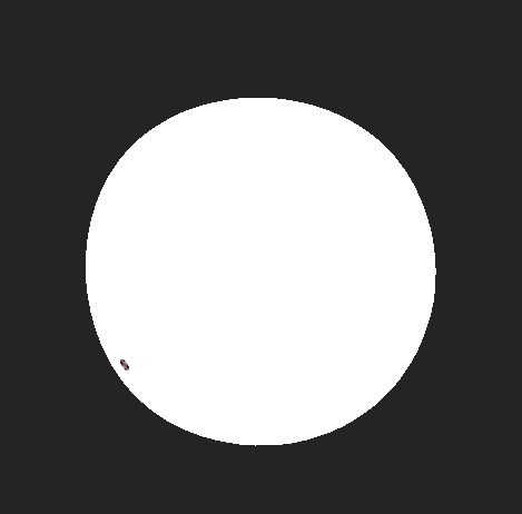
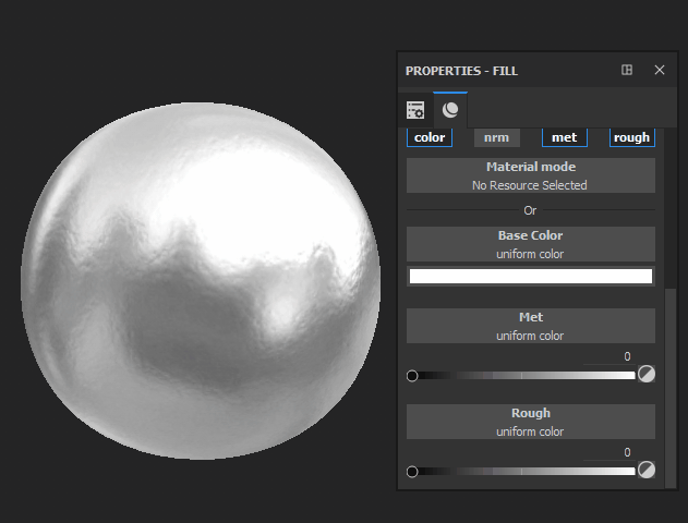
If you see that the whole model is white and you can draw Base color on it, then you did everything right. Now you can save the project and go to the next section.
If the model is pink, then most likely there is an error in the shader – a notification about this will be in the console.
Building a shader in Substance Painter
Consider the structure of a shader using the previously described unlit shader as an example.
The shade method is the basic part of the shader; it will not work without it. Everything that will be described inside can be displayed on a 3D model. All final calculations are displayed through the function diffuseShadingOutput ().
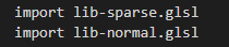
Lines 3 and 4 create a parameter and a variable, respectively. The parameter associates the Base color channel with the variable in which the painted texture will be stored. All parameters are registered in help, in the case of Base color everything should be spelled out as in the example. Line 8 lays out the texture in the uv-coordinates of the 3D model. I note that for texture with Base color the system is used Sparse virtual textures, because the first line connects the library lib-sparce.glsl.
You can find many implementations of Matcap’a, but its main point is that the normals of the model are directed towards the camera and the texture is rotated along the x and y axes. To rotate the normals towards the camera, we need a view matrix, or a view matrix. You can find one in helpreferred to above.

So, these are the same declared names as in the case of Base color. Now we need to get the normals of the 3D model.

Zero as the fourth element of the vector is required.
Multiplying a view matrix with a normal vector will expand the normal to the camera.

Do not forget that when multiplying matrices, the order of the factors is important. If you change the order of multiplication, the results will be different.
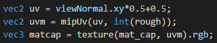
Can now from viewNormal create uv coordinates.

It’s time to hook up the matcap texture.

In this case, the parameter will create a texture field in the shader interface, and if the project has a texture with the name “Matcap_mip”, then Substance Painter will automatically pull it up.
Let’s check what happened.
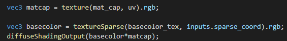
Here Matcap’s texture is expanded in new coordinates and multiplied with Base color at the output. I want to pay attention to the fact that the Matcap texture is expanded through a function texture (), and Base color – through the function textureSparse (). This is because the textures specified through the shader interface cannot be of type SamplerSparse.
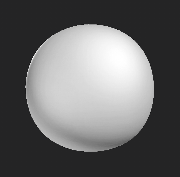
The result should look something like this:

Now add a mask that will mix two Matcap’s. For convenience, add two Matcap’a in one texture, breaking them into channels. As a result, two Matcap-textures will be in the channels R and G, respectively.
You get something like this:

Let’s start adding a mask to the shader. The principle is similar to the addition of Base color.

It is enough to replace the basecolor value with user0 in the parameter.
Now get the mask value in the pixel shader and mix the matcap textures.
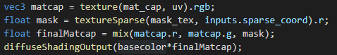
Here, only R channel is used in the mask, because it will be black and white. The two matcap channels are mixed using the function mix () – An analogue of lerp in Unity.
Let’s update the shader and add custom channels in the interface. To do this, go to Window / Views / Texture Set Settings, in the window near the Channels heading, click on the plus and select user0 from the large list.

The channel can be called anything you like.
Now, drawing on this channel, you can see how the two Matcap textures are mixed.
The shader for Unity also used normal maps for Matcap, which were baked from a high-poly model. Let’s try to do the same in Substance Painter.
To use all operations on normals, you need to connect the appropriate the library:
Now connect the normal maps. There are two of them in Substance Painter: one is obtained by baking, and the second can be drawn.

From the parameters you can guess that channel_normal Is a normal map that you can draw on, and texture_normal – baked normal map. I also note that the name of the variable texture_normal sewn into the API and you can’t name it at your discretion.
Next, unpack the cards in the pixel shader:

Then we mix the normal and normal maps that are on the vertexes of the model. To do this, in the library connected above, there is a function normalBlend ().

First we mix the two normal maps, and then the normal normals. Although it doesn’t really matter in which order to mix them.
The rotation of the normals in the direction of the camera will look like this:

Then you can not change anything, everything will remain the same. It should be something like this:
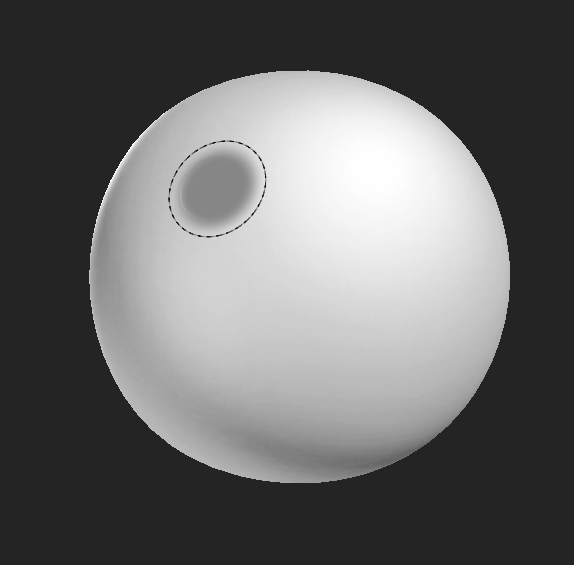
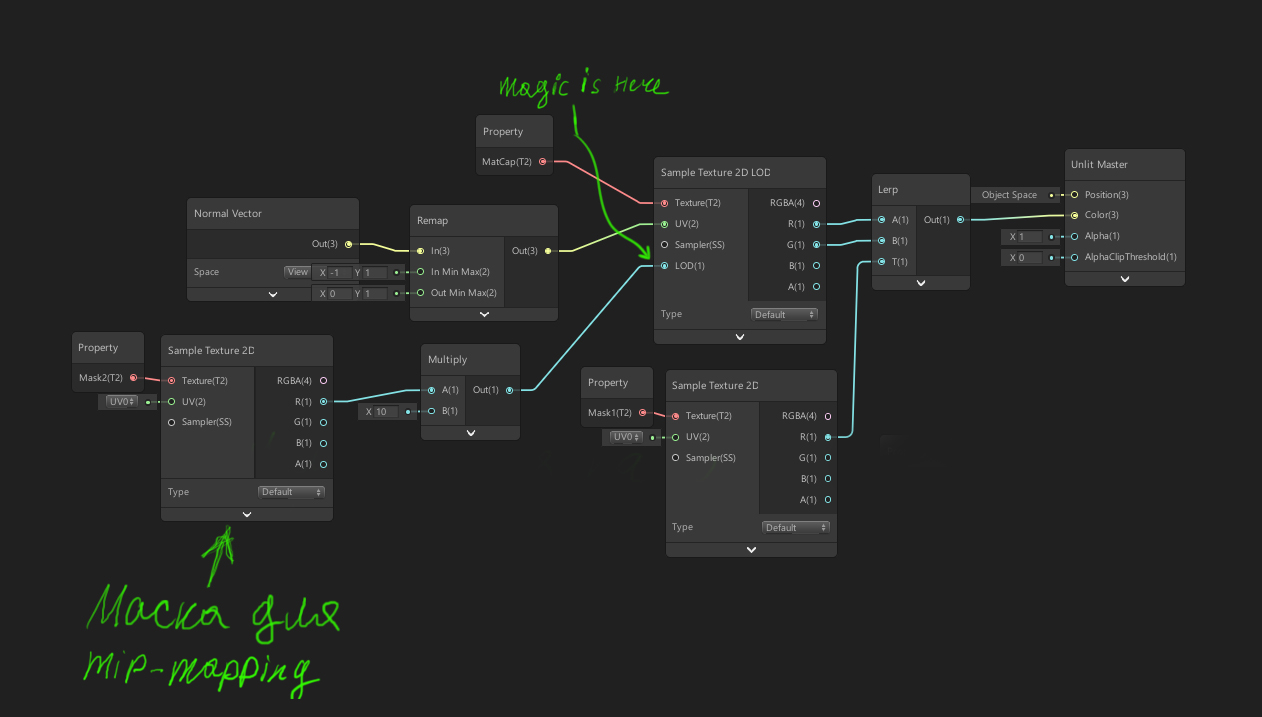
Mip-mapping, as mentioned above, in this case is needed to simulate scuffs, something like a roughness card in PBR shading. But the main problem is that the pyramid from mip-cards is not generated for the texture, which is transmitted from the shader interface, and accordingly the method textureLod () from glsl will not work. One could go the other way and load the Matcap texture through the user channel, as was done to mix Matcap’s. But then the quality of the texture will greatly decrease and strange artifacts will appear.
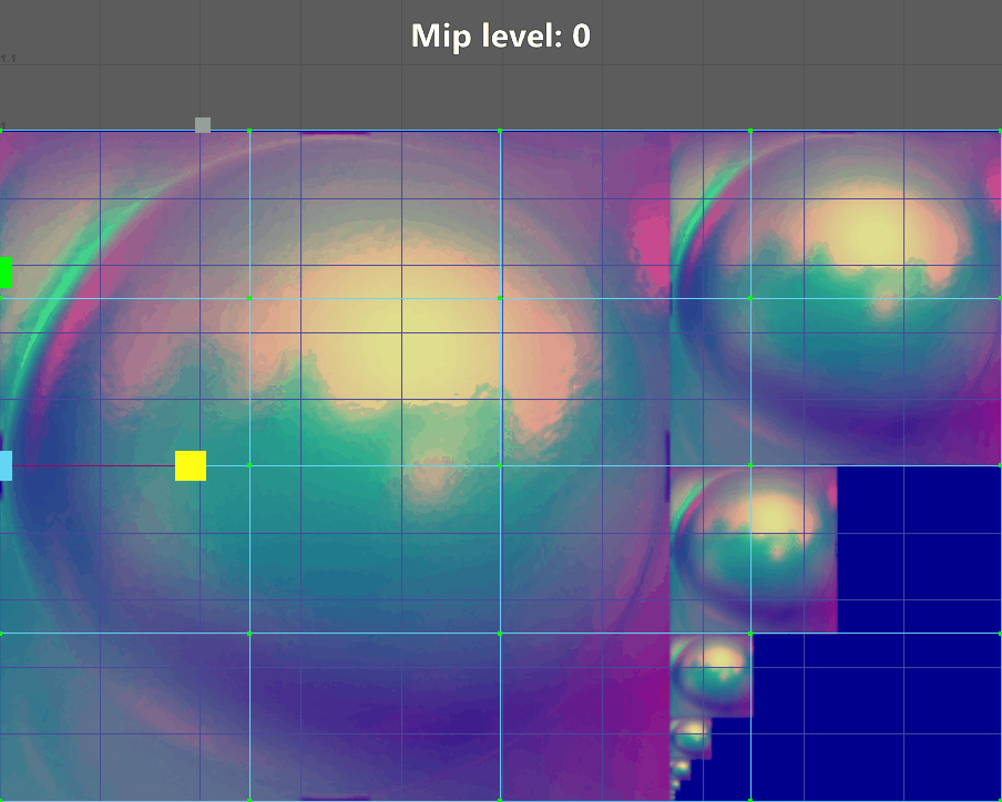
An alternative solution is to create MIP card pyramid manually, in Adobe Photoshop or another similar editor, and then select the MIP level. The pyramid is built quite simply. It is necessary to proceed from the size of the original texture – in my case it is 256×256. We create a file with a size of 384×256 (384, because 256 + 256/2) and now we reduce the original texture by half until it is one pixel in size. All versions of reduced textures are placed to the right of the original texture in ascending order. It should look like this:

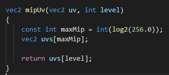
Now you can start writing a function that will find the coordinates of each texture in the pyramid, depending on the color of each pixel on the mask.
The easiest way is to store the uv coordinates that will be calculated for each texture in an array. The size of the array will be determined as log2 (height). We need original uv, so add them to the function argument. To determine which element of the array to use on a particular pixel, add level into the function argument.
Now calculate uv for the original texture, that is, crop those extra 128 pixels in width. To do this, multiply the x coordinate by ⅔.

To use the rest of the texture from the pyramid, you need to find patterns. When we created the pyramid from the textures, we could notice that each time the texture is reduced by half from the previous size. That is, how many times the texture size decreases, can be determined by raising 2 to a power MIP level.

It turns out, if you select level, for example, 4, then the texture will decrease by 16 times. As uv-coordinates are determined from 0 to 1, then the size needs to be normalized, that is, 1 divided by how many times the texture has decreased, for example, 1 divided by 16.
Using the obtained value of the size variable, you can calculate the coordinates for a specific MIP level.
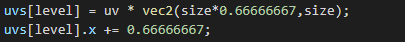
The size uv decreases the same as texture size. At the x coordinate, the texture always shifts by ⅔. The y coordinate shift can be defined as the sum of all the values of the variable size for each value level. That is, if the value level = 1, then uv along the y coordinate will shift by 0 pixels, and if level = 2, then the shift will be half the height of the texture – 128 pixels. If level = 3, then the shift will turn out as 128 + 64 pixels and so on. The sum of all shifts can be obtained using the cycle.
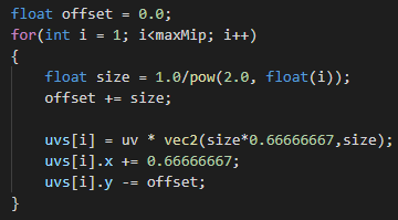
Now every iteration a variable offset will summarize and shift the texture along the y axis by the desired number of pixels. The step-by-step algorithm looks something like this:
The last step is to display the channel that will select the desired level on each pixel. We have already done this, nothing new.

To choose a texture MIP levelIt’s enough to multiply the length of the array by the texture. Now you can connect new uv-coordinates through the method just written.
Do not forget to translate the texture into int type, since this is now an index for the array.
Next, you need to add a custom channel in Substance Painter, as we did before. It should be like this:

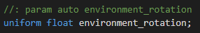
The only thing missing for the shader is the light source and the ability to rotate it by pressing shift. First of all, we need this parameterwhich will give the angle of rotation by pressing shift, and rotation matrix.

We randomly place the light source and multiply the position by the rotation matrix.

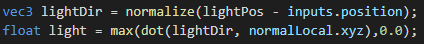
Now the light source will rotate around the y axis by pressing shift, but so far this is just a vector in which the position of the light source is stored. There is good material on how to implement directional light in a shader. We will focus on him. It remains for us to determine the direction of light and the illumination of our model.
The color of the shadow and the color of the light source will be set by the parameters:
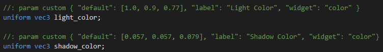
Color parameters are interpolated based on the illumination calculated above.
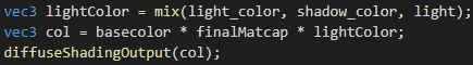
It turns out like this:
Using these parameters, you can adjust the color of the shadow and the color of the light source through the Substance Painter interface.
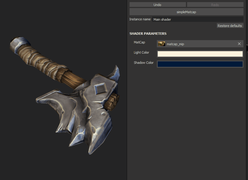
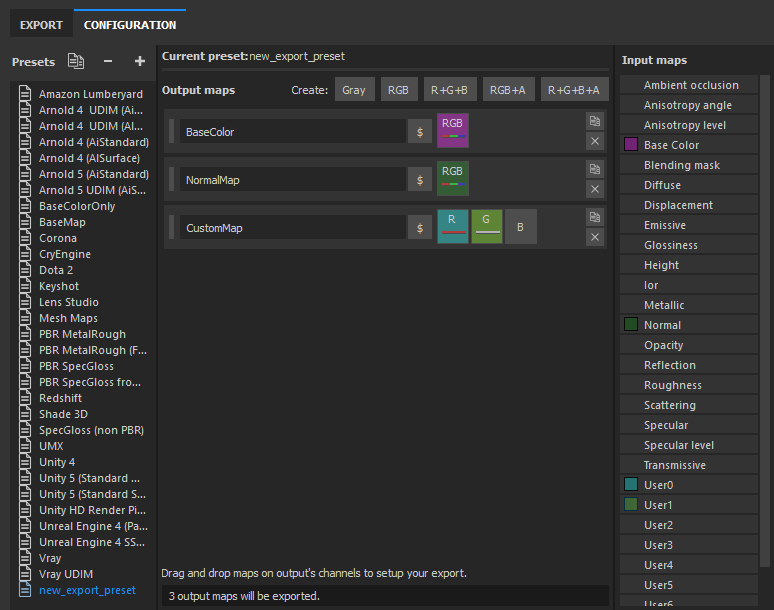
Create and configure a preset
When the shader is ready, you need to import the Matcap texture and the shader with the shelf setting.

We remove all unused channels and add user channels:
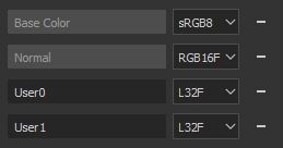
A preset for exporting textures will look like any other, except that it will use our custom channels.
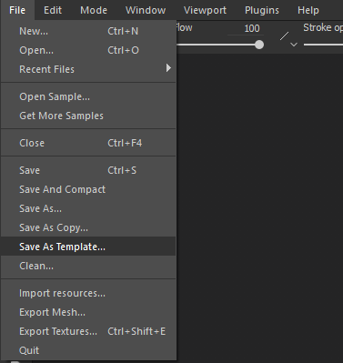
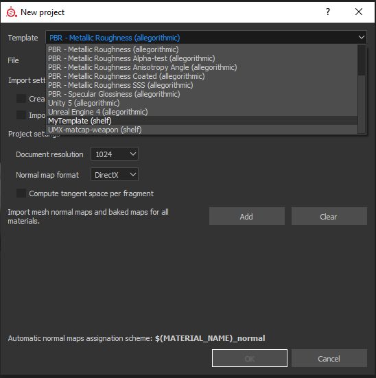
We’ll create a template for all the settings so that when you create the project, the desired shader is immediately assigned and all the texture channels are configured. To do this, go to File / SaveAsTemplate and save the template.
Now when creating a new project, you don’t need to configure anything – just select the desired template.
What did you get
A technical artist can create special effects, customize scenes, and optimize rendering processes. I also wanted the armor and weapon models in Stormfall: Saga of Survival to be exactly what 3D artists intended. As a result, the 3D model in Substance Painter looks the same as in the game engine.
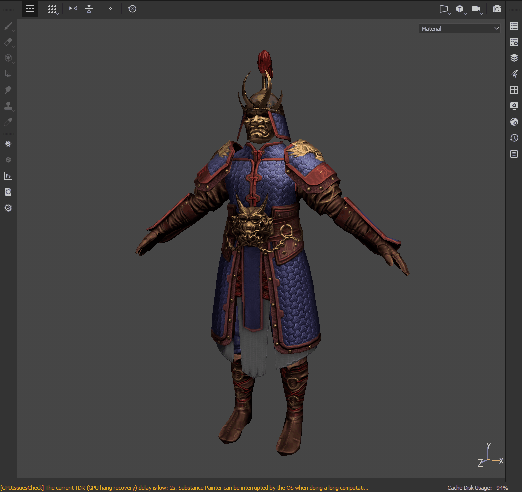
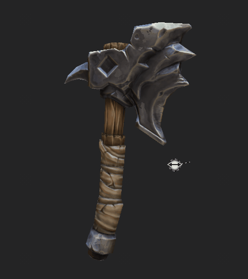
3D model in Substance Painter with custom shading.
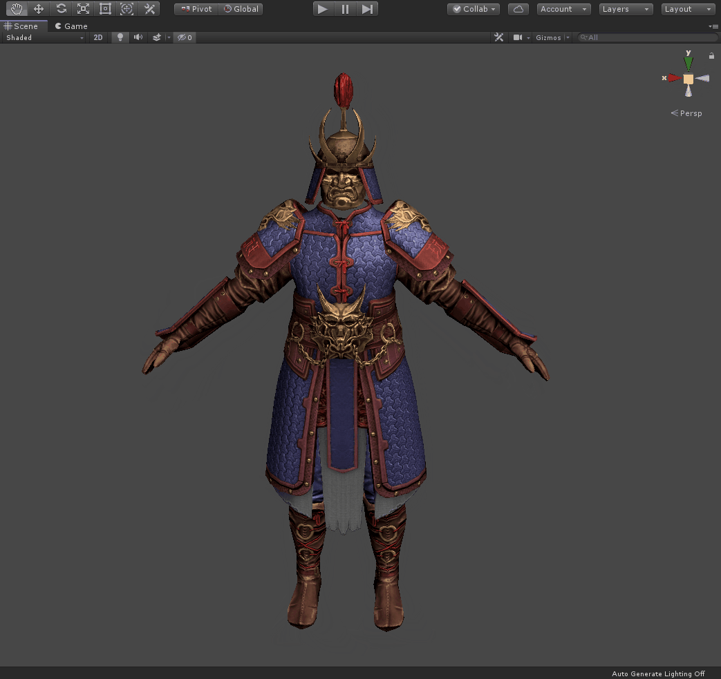
3D model in Unity with custom shading.
I hope the article was useful and inspired you to new achievements!


Is the matcap texture have any encoding problem?