“Extruder” of filament for a 3D printer with your very skillful hands
A little background
In my first article, they didn’t stuff me with a Panama hat and you, dear community, accepted it quite favorably, which means that if you want to do a good deed, no obstacles or destruction will stop you)))). In addition, I received feedback, including through personal messages, in which I was able to discuss many important issues, for which I am especially grateful.
As you could conclude from my first article, I represent an explosive mixture of an engineer-textile-chemist-polymer-scientist… trying a little “into science”.
The experiments don't stop. The constructed prototype periodically reveals the disadvantages of the implementation, but this is only the result of the dendro-fecal method of design on the knee and deliberately ignoring some important design postulates… Nevertheless, now we can safely say that the principle of operation shows good and necessary results and Using my experience and identified errors, you can implement everything yourself.
Even at the stage of creating a prototype and developing the technology, I asked myself the question “Who needs this in everyday life?” One of the answers came from my friend and comrade who needed filament for a printer.
Having briefly studied the issue, it became clear that the issue is relevant for prosaic commercial reasons (the average price of a coil of filament is 1000 rubles versus 80 rubles for granulate, which is somehow inhumane), and therefore numerous attempts are being made to create various types of extruders.
Therefore, if we are not talking about commercial use of the design, please – WTFPL.
Let me note in advance that I hope the article will not be finished, but will turn into a guide to action and, thanks to your assistance and comments, we will all together bring the design to some perfection.
Among the current essential issues for the stated purpose:
The existing prototype allows loading approximately 400 g. granules or scrap of absolutely any thermoplastic polymer (I am actively experimenting with PP, ABS, PFA, PEEK, PA and some others, as well as with oligomers, resins and other thermosetting polymers, rubbers and others). The issue of continuous nutrition requires discussion (either continuous nutrition or expanding the loading volume to the required conditional 1 kg). Again, a question of expediency, since an increase in loading volume will entail an increase in size, the use of more powerful heaters and, as a consequence, an increase in energy consumption, etc. It would also be nice to carry out a detailed thermal engineering calculation to select a heater of optimal power.
With the current “needle” size, the maximum stable thread thickness I got was 1 mm, which, strictly speaking, is not enough since the standards provide for 1.75 and 3. Due to the fact that it is not possible to carry out volume calculations, it is necessary to select experimentally the required diameter (for which it is designed to be removable) and according to thermal calculations, it is advisable to adjust the height of the “needle” so that the polymer, which is already beginning to crystallize, reaches the “tip”. In general, you can take my drawings as a basis and use the current height of the “needle” to design the device, just play with its shape (a small remark, conical is also possible) and diameter (currently the diameter is 15 mm, I think 20 should be enough).
Frankly speaking, due to the lack of a printer itself, I did not really implement the feeding device. And here the question arises! Is a feeding device necessary at all if the power supply is Bowden type and you can directly power the print head? In this case, in principle, heated filament will be supplied to the print head, and this simplifies printing (take at least the aspect of reducing the power of the heater in the head or the absence of the need to “dry” the filament)…
There are a lot of questions and here I hope, among other things, for your printing experience and feedback.
Subject-wise.
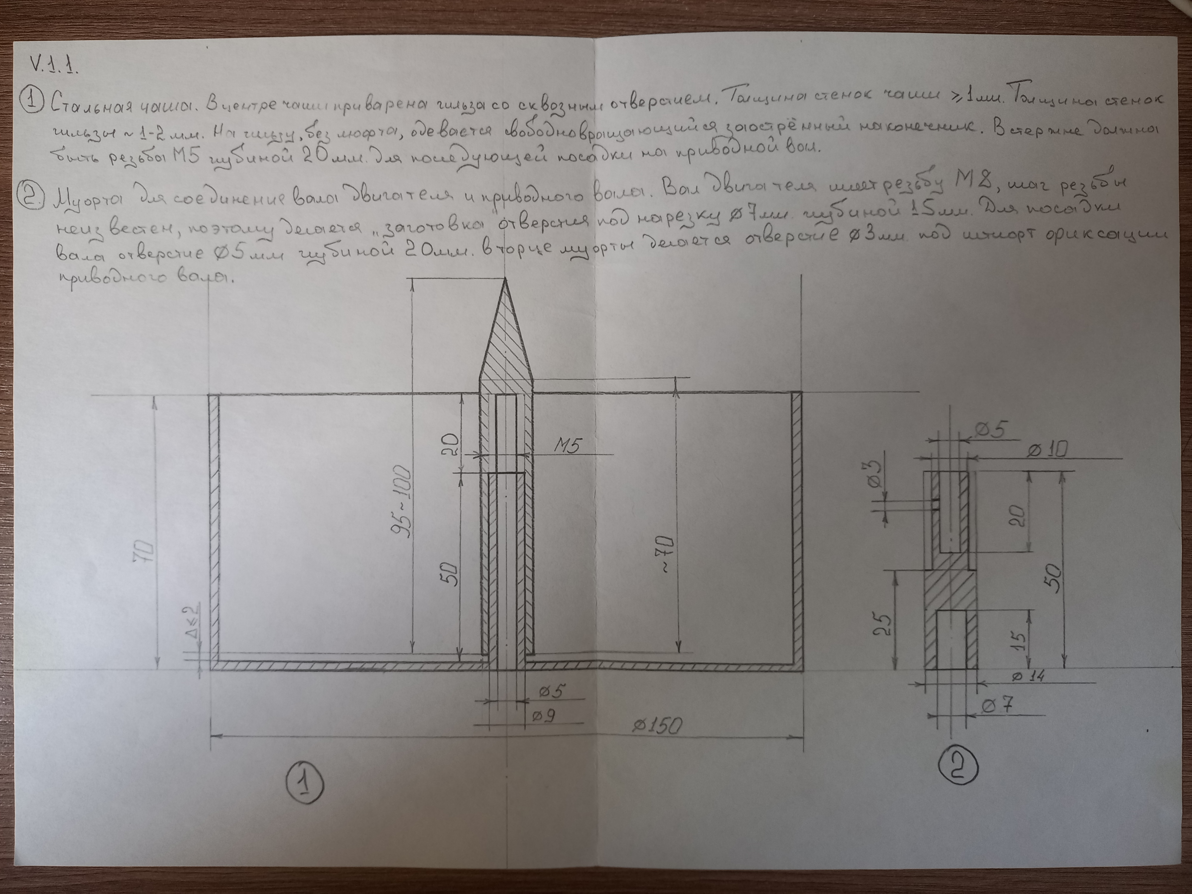
Let's start with the main drawing that was sent to the turner.

This is the main node. An important nuance – in the drawing and further photos I did not photograph the lid, which is put on top and has a 22 mm hole in the center. necessary for two reasons: 1 – ensuring uniform heating of the mass; 2 – reduction of the smell of burnt plastic.
My plastic burns for one simple reason – a low-quality micanite heater (even though it’s ours, domestic, I won’t indicate where I ordered it, so as to avoid misunderstandings, maybe this is an isolated case), this resulted in uneven heating (it showed up when measured with a pyrometer – at a given temperature for polypropylene, for example, zones of about 130 degrees, somewhere 200 degrees, somewhere 280 degrees without identifying any pattern related to the placement of heating elements over the area of the heater as a whole).
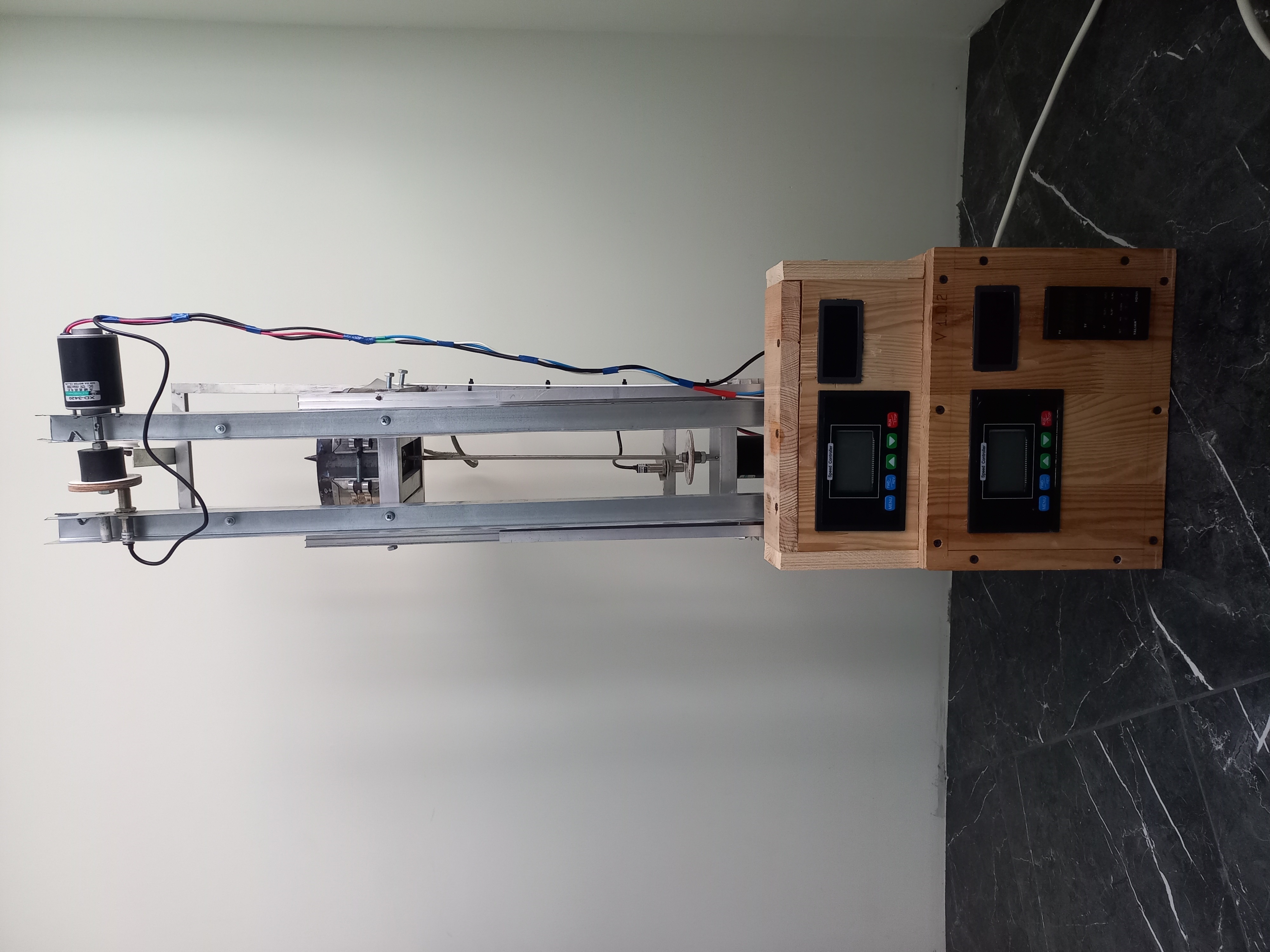
The design kit consists of: PID controller with a thermocouple included (but I used a thermocouple in the heater body, the PID controller itself can work with various types of thermocouples, it has been working properly for 3 years already), Drive shaft (diameter 5 mm. length cut to 500 mm.) from engine through the speed controller (unfortunately I can’t find one on Ali, the product card has disappeared), speed control through tachometer (in practice, for most polymers it did not raise more than 90 rpm). This whole 12-volt thing is powered by a 500-watt power supply taken from the same Ali (I just took it at one time for experiments).
But now the main mistake is that the shaft drive must be strictly through a gearbox, now from the same Ali I’m waiting for a set of gearbox and motor from a 12 V screwdriver. The broach (extraction) is now also being converted to a single design with a gearbox and a pressure shaft due to the fact that the engine produces at least 50 rpm through the speed controller. which is a lot for my purposes.
General view of the structure

The case is assembled from the remains of a furniture panel after repair (put all the wires and connections in order), it can be reduced many times due to the fact that the components are small in size, it was not critical for me.
The main frame is assembled from profiled aluminum and welded with a torch on castolin rods for aluminum with flux 192 FBK – the connection is like a monolith, it cannot be torn along the seam. The height was taken based on the height of the engine and the length of the shaft. For the indicated purposes, the shaft can be 12-15 cm. – this is quite enough, but in short it is impossible – it will lead to unnecessary heating of the shaft drive from the bowl.
This is where I end for now. I present it to your judgment))))
Based on your comments, questions and comments, I will be happy to correct it.


