Why does a Microcontroller Programmer need Linear Algebra (or How to find the angle between vectors?)
Prologue
In programming, the task often arises of finding the angle between vectors. For example, you are writing firmware for a PTZ camera. You have a sensor for the current position of the lens. And there is the desired direction of the lens position. You need to calculate the error in degrees. You need to determine the sign of the error and decide which way to turn in order to expend minimal energy and time.
 is more optimal")
Purely formally, between two vectors you can see two angles: the one that is counted clockwise and the one that is counted counterclockwise. In this example, it is logical to rotate the camera clockwise.
Now, instead of a PTZ camera, we install a radar antenna and come to the conclusion that we need to solve the same problem: find the angle between the vectors.
Then, in SDR processing in digital PLLs, it is necessary to find the phase difference between two complex numbers (essentially vectors).
I have had to solve the problem of finding the angle between vectors so often that I decided to write a note about it.
Definitions
A scalar is a number that does not depend on the choice of coordinate system. A scalar is always described by a single number
Vector is a mathematical object that has magnitude and direction. Simply put, a vector is a directed segment. An example of a vector is a compass needle, or the direction of the wind in a given area. The complex number a+j*b can also be considered as a vector on the plane.
Scalar product vector is an operation on two vectors, the result of which is a scalar. If the angle between the vectors is straight, then the scalar product is equal to 0.
Determinant is a scalar quantity. Used when calculating the cross product.
Vector artwork – a vector perpendicular to both original vectors, the length of which is numerically equal to the area of the parallelogram formed by the original vectors, and the choice of two directions is determined so that the triplet of the vectors in order in the product and the resulting vector is right
Formulation of the problem.
Two vectors are given on surface Va=(xa,ya,0) and Vb=(xb,yb,0). The question is to find the angle between these vectors in degrees (this is more common). Also determine the sign of this angle (+ or -).
Obviously, this angle between the vectors can take values from -180…0… 180 degrees. Or -pi….pi radians. No more, no less.
To begin with, as usual, let's outline unit tests. So that we understand what we are doing and why? What result do we expect and what do we want? All this should be reflected in the list with unit tests. Only then rush to write code. This is obvious…. Here is a list of these tests.
number | Vector A | Vector B | expected angle | ||
test | a_x | a_y | b_x | b_y | degrees |
1 | 1 | 0 | 0 | 1 | +90 |
2 | 0 | 1 | 1 | 0 | -90 |
3 | 0 | 0 | 0 | 0 | The angle is not defined. Can be any angle. |
4 | 1 | 1 | 1 | 1 | 0 |
5 | 1 | 0 | -1 | 0 | 180 |
6 | 1 | 0 | -1 | -1 | -135 |
7 | 1 | 0 | -1 | 1 | 135 |
Solution
To calculate this angle you will have to use linear algebra and analytical geometry. Classic way of calculation angle module between vectors is the scalar product. Even a schoolboy knows about this.
As you know, the angle between vectors shows the scalar product. You give two vectors, you get a number. By definition, the scalar product is equal to the product of the lengths of the vectors and the cosine of the angle between them (the scalar product for two vectors with coordinates (a_x; a_y) and (b_x; b_y) is calculated by formula (1)

As you can see, the scalar product is maximum when cos=1, that is, the angle is zero. At the same time, the dot product is 0 when the vectors are orthogonal (angle 90 degrees).
From equation (1) we can express theta
Hidden text
\theta= arccos ( \frac{a_xb_x+a_y b_y }{\left |\overrightarrow{a} \right | \left |\overrightarrow{b} \right |}) \qquad \qquad \qquad (2)

In the denominator, the lengths of the vectors are multiplied.

But here's one problem. Formula (2) only gives module this angle. And for all kinds of automatic control systems, SDR processing, you also need sign angle (+ or -) given that the vectors form a right-handed triple. Yes. Like this..

This is where you start reading institute mathematics: matrices, determinants, vectors, etc. The sign will already determine us vector product. The idea is very simple. We will calculate the cross product [a,b] and look at the sign of the z component of the resulting result. Essentially, the sign of the angle is the sign of the determinant for the vector k. This will be the sign of the angle between the vectors.
![\left [ \overrightarrow{a}, \overrightarrow{b} \right ] = \begin{bmatrix} &\overrightarrow{i} &\overrightarrow{j} &\overrightarrow{k}\\ & a_x &a_y &0\\ & b_x &b_y & 0 \end{bmatrix} = (0,0,a_xb_y- a_yb_x)\qquad (3)](https://habrastorage.org/getpro/habr/upload_files/16d/e98/12b/16de9812b7920fad4420f1e5fc8010ee.svg)
It turns out that the final formula for the angle between vectors crystallizes into this form

Cumbersome? Yes. That's it… What did you want? Mathematics…
Software part
Any math is best done in C. Then you can run the code on any platform. On various microcontrollers, in the Linux kernel, in User Space and other programs.
typedef struct  {
    double dx;
    double dy;
    double dz;
} Vector_t;


bool is_double_equal_absolute(double d1, double d2, double precision) {
    bool res = false;
    qWord_t w1;
    qWord_t w2;
    w1.val = d1;
    w2.val = d2;
    if(w1.num == w2.num) {
        res = true;
    } else {
        if(((d1 - precision) <= d2) && (d2 < (d1 + precision))) {
            res = true;
        } else {
            res = false;
        }
    }
    return res;
}

bool double_is_zero(double value) {
    bool res = false;
    res = is_double_equal_absolute(0.0, value, 0.000001);
    return res;
}

double dot_product(const Vector_t*const  v1,  const Vector_t* const v2) {
    double dot = 0.0;
    dot = (v1->dx) * (v2->dx) + (v1->dy) * (v2->dy) + (v1->dz) * (v2->dz);
    return dot;
}

double norm(const Vector_t* const Node) {
    double norm=0.0;
    if(Node) {
        double argument=((Node->dx) * (Node->dx)) + ((Node->dy) * (Node->dy)) + ((Node->dz) * (Node->dz));
        norm = sqrt(argument);
    }
    return norm;
}


double math_sign(double val) {
    if (0.0 < val) {
        return 1.0;
    }
    if (val < 0.0) {
        return -1.0;
    }
    return 0.0;
}


/**/
double calc_angle_between_vectors_rad(
        const Vector_t* const v1,
        const  Vector_t* const v2) {

	LOG_DEBUG(MATH,"V1:%s",VectorToStr(v1));
	LOG_DEBUG(MATH,"V2:%s",VectorToStr(v2));

    double betta_rad = 0.0, norm1, norm2, absBetta_rad;
    double dotPr;
    Vector_t v3;
    norm1 = norm(v1);
    norm2 = norm(v2);

    bool res1= double_is_zero(  norm1);
    bool res2= double_is_zero(  norm2);
    if (res1 || res2) {
        return 0.0;
    } else {
        dotPr = dot_product(v1, v2);
        absBetta_rad = acos(dotPr / (norm1 * norm2));
        // scalar multiplication gives just module of  the angle.
        // vector multiplication gives the sign of the angle.
        v3 = cross(v1, v2);
        if ( double_is_zero(v3.dx) && double_is_zero(v3.dy) && double_is_zero(v3.dz)) {
            betta_rad = absBetta_rad;
        } else {
            betta_rad = math_sign(v3.dz) * absBetta_rad;
        }
    }
    LOG_DEBUG(MATH,"AbsTheta:%f rad,Theta:%f rad",absBetta_rad,betta_rad);
    return betta_rad;
}
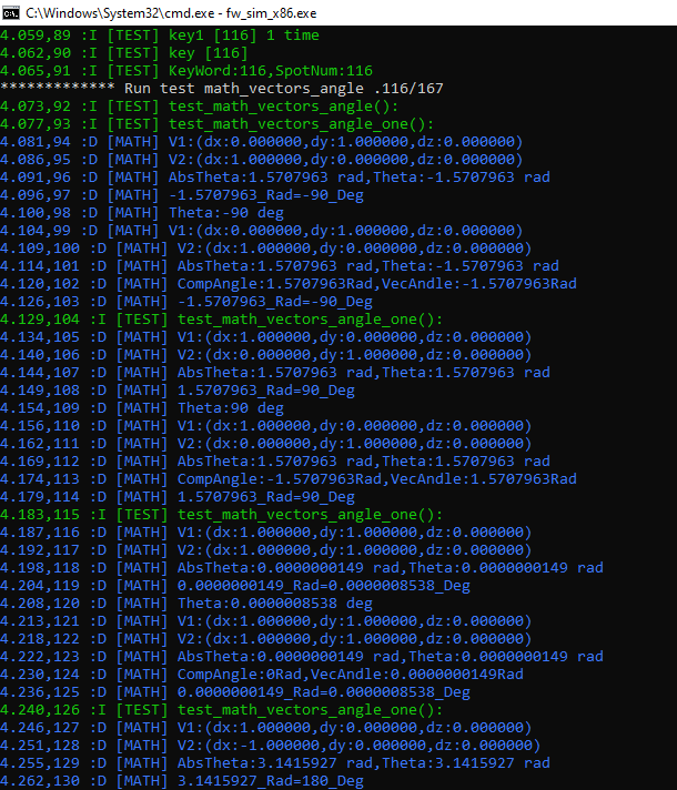
Debugging
I wrote a console application to test the function of calculating the angle between vectors. As you can see, the tests are passing. So the algorithm works.
Here are some more calculation results.
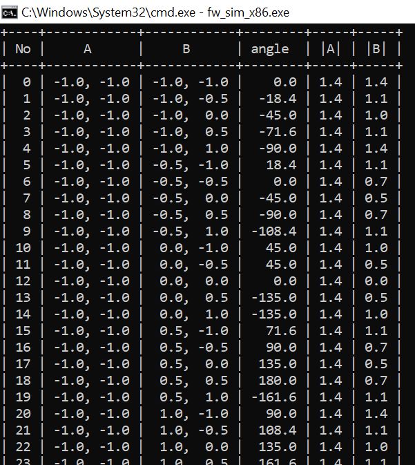
The function works.
Advantages
++Formalness, simplicity and clarity. A wide range of well-known and generally accepted mathematical methods of linear algebra are used.
Flaws
–This method of calculating the angle between vectors is very intensive from a computational point of view. There are two roots, arc cosine, multiplication and addition.
Where do you usually need to calculate the angle between vectors?
–Wherever there is a need to turn something: PTZ cameras, heavy mills, wind generators, turrets, cranes, directional antennas (YAGS, parabolic, AFARs), geodetic theodolites, solar panels. There, the task constantly arises of aiming the rotating support platform at some target.
–In SDR processing on the receiver side (both real-time and post-processing(e)) there is such a thing as phase detector. The phase detector is part of the PLL circuits. From a software point of view, a phase detector is precisely the angle between the vectors that are formed by two complex numbers: the phase from the LocalOscullator (LO) and the phase from the output frequency divider.
Results
We managed to learn how to calculate the angle between vectors. The angle calculation algorithm works.
As you can see, to determine the angle between vectors you need to know trigonometry, linear algebra, (scalar product, vector product) and so on.
It would be great if such an operation as finding the angle between vectors was implemented at the hardware level directly among the set of commands supported by assembler.
Dictionary
Acronym | Decoding |
PTZ | Pan Tilt Zoom |
SDR | Software-Defined Radio |
PLL | Phase-locked loop |
CCW | Counter Clock Wise |
CW | Clock Wise |
PLL | Phase locked loop |
Links
http://latex.codecogs.com/eqneditor/editor.php
https://rsdn.org/forum/alg/4415389.hot
Stepper motor control theory (or how to rotate a PTZ camera) https://habr.com/ru/articles/709500/