We control the Home Assitant smart home through Alice and without the Internet. Part 1

The article will be divided into several parts to describe in more detail all aspects of this topic.
In this part I will talk about the problem and the approach to solving it.
Preface
When I read the announcement of the Yandex Station Midi, I was delighted to have a Zigbee module inside this tiny module and to improve the processing speed of smart home control commands several times, but I learned in more detail that the acceleration of processing only affected zigbee devices that I already connected to a Home-based smart home Assistant. The idea came spontaneously, but we managed to figure out how to force Alice to send commands to Home Assistant and organize communication at the “coordinator-to-coordinator” level.
Task
Zigbee in a smart home “out of the box” does not imply connecting the “coordinator-coordinator” format, and in general this does not sound entirely logical, however, since the Midi station and the smart home were coordinators, it was necessary to make an additional node in the network that would allow one of the two, think that it communicates with the end device.
Problem
Despite the simple solution in view of the interlayer, we have a log in the wheel of our machine of revolution in smart home control – the end device can only be connected to one Zigbee network.

We connect “mother-mother” with a “male-male” adapter
Since our two devices can only issue commands to end devices, the solution to the problem is quite simple – you need to make a layer that will say in both directions that it is the end device and relay commands from one coordinator to another, receiving a command from one and updating the state for another. The solution to this problem is an ESP32 controller with Zigbee support. However, a logical question may arise – how to transmit both a command and a state change to two coordinators, if the end device can only be connected to one network? The answer is simple – not at all. (a curtain)
In fact, this is why the ESP32 controller is used. We receive a command from the station via Zigbee, and then for Home Assistant we transmit information about state changes via USB. Bingo, but how?

Integration
As you may have noticed, in solving this problem I used an ESP32-C6 board, which has support for Zigbee 3.0, which will give us the ability to connect to a Midi station.
Let's move from theory to practice. We bought the board, figured out what to do with it, but how to force Home Assistant to accept state changes? And again Bingo is a layer in the form of integration. Unfortunately, there is quite a bit of information on the Internet about how to develop your own integrations for Home Assistant, so I would like to include this block in a separate article to show, using the example of this integration, how to develop, install and upload your developments to the integration store. Therefore, for now we will make do with screenshots.
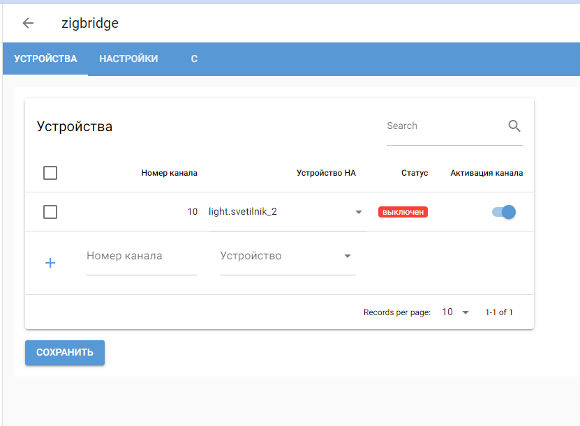
I wrote a small web interface integration in which we link a device's Zigbee channel to a device in Home Assistant. Unfortunately, at the moment there is no link to the repository, since the integration is not yet ready for a stable version.

The principle of integration is not complicated:
We look for our ESP32-C6 among the USB devices, connect via the serial port and transmit the list of channels that we need to listen to.
When the state changes on the station side, ESP transmits an array of the format {'c':10,'st':0} via USB JSON, which means channel 10 has received the state off.
Through the Home Assistant API, we send an on\off event to the corresponding channel of the device depending on the received status.
What does it all revolve around?
The integration reads device status information from the board’s serial port. How exactly this is implemented, let's figure it out.
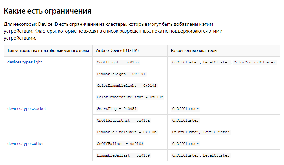
Since the root task is for a station to be able to change the state of something, this “something” must be supported by the station itself. What can we turn on and off, have customizable parameters (brightness, color) and also store information about it? That's right – a light bulb! In addition, according to Yandex documentation, this type of device is the “richest” in terms of possible attributes.

But if we have one board, how will we manage multiple devices? Here the implementation of the Zigbee protocol itself helps us. Each physical device can have several component devices (for example, a humidity and temperature sensor can also contain a light sensor), and each such device is initialized separately, ultimately representing several independent devices for the coordinator. We will just use this “feature” of the protocol, creating a switch for each of the given channels (according to the Zigbee classification this is called Endpoint).
To implement this “deception” of the station, I used firmware based on the ESP‑IDF framework as a basis, which will give us the opportunity to flexibly configure the board for our tasks. The principle of operation of the firmware is as follows: When turned on, the board immediately waits for the list of channels to be entered from the serial port; as soon as our integration has transmitted the list, the light device is initialized for each of the specified channels (endpoints), after which our ESP board is connected to the station network . Now, if we enable the search for devices on the station, we will see as many “light bulbs” as there are channels we have specified in the integration. In order to know which channel to assign what to, the integration has added a channel status display, so we simply turn on each of our “lamps” in order and look in the integration to see which channel is turned on.
As a result, we get engineering magic with crutches outside of Hogwarts, a demonstration of which you can watch in this video (recorded for a friend, that’s why it’s a “free” format):
What's next?
In the next part, we will look at how to create your own integration for Home Assistant from scratch to installation in the system, and we will also look at the implementation of the firmware on the ESP-IDF.
PS
This is my first publication, so please throw soft slippers, preferably not in the face.
I would also like to tell you that I had plans to create a commercial “whistle” to implement the Plug’n’Play approach for that audience that would not like to “mess around”, but simply connect and use. If you are interested in this device, let me know in the comments, I’ll tell you more about it.


