SIM800L + STM32 Bluepill + Rust. How is it?

Several years ago, I made myself a monitoring unit for the power supply of a country boiler from UPS on Arduino. As practice has shown, the Arduino MEGA + shield on the SIM900 with standard libraries is very unstable. From time to time everything freezes, overloads itself, etc. It is impossible to debug this, so I started looking for other options. As a result, I decided to redo everything using modern technologies: I took STM32 Bluepill as a basis, bought a SIM800L module on Ali, but most importantly, I decided to write all the code in Rust, bought into the promises of its high reliability. Read on to learn from this.
Functionality
A few words about what I wanted to get from the new homemade product.
I have an UPS Inelt in my dacha, which has an RS232 port for controlling the UPS. It supports the rather ancient Megatec exchange protocol, with which you can perform simple actions to control the UPS and find out its current state. I was not particularly interested in the management, but I wanted to know the state of work: how is the mains voltage there, are the batteries alive, etc. On the market I did not find ready-made solutions that could solve this problem, so I decided to do everything myself. Everything in the spirit of DIY.
Megatec protocol
Megatec Protocol information
                        VERSION : 2.7

                        DATE : SEP. 30, 1995

		DATE	:V2.7	: JULY 30 ,1996

DATE	DESCRIPTION	MODIFY BY
2.6	95-9-30	UPDATE "D" COMMAND (SS.SS -> SSS.SS)	Kevin Chiou
2.7	96-8-01	Disable "D" COMMAND	Kevin Chiou

A. General: This document specifies the RS232C communication protocol of
            the Advance-Intelligent UPS. The protocol provided the following
            features :

            1. Monitor charger status.
            2. Monitor battery status and condition.
            3. Monitor the utility status.
            4. Provide the power switch function for computer to turn on and
               off the utility on schedule for power saving.

            Computer will control information exchange by a query followed by
            <cr>. UPS will respond with information followed by a <cr> or
            action.

B. Hardware:

            BAUD RATE............... : 2400 bps
            DATA LENGTH.......... : 8 bits
            STOP BIT..................... : 1 bit
            PARITY........................ : NONE

            CABLING :

               COMPUTER                  UPS
            ===================================
                  RX   <----------   TX  (pin 9)
                  TX    ---------->  RX  (pin 6)
                  GND  <----------   GND (pin 7)

                  (9 pins female D-type connector)

C. COMMUNICATION PROTOCOL:

1. Status Inquiry:

Computer : Q1<cr>
        UPS      : UPS status data stream, such as
             (MMM.M NNN.N PPP.P QQQ RR.R S.SS TT.T  b7b6b5b4b3b2b1b0<cr>

        UPS status data stream :
	There should be a space character between every field for data
	separation. The meaning of each field is list as followed:

                a. Start byte    : (

		b.I/P voltage   : MMM.M
                  M is and integer number ranging from 0 to 9.
                  The unit is Volt.

                c.I/P fault voltage : NNN.N
                  N is and integer number ranging from 0 to 9.
                  The unit is Volt.

                  ** For OFF LINE UPS**

                    Its purpose is to identify a short duration voltage glitch
                  which cause OFF line UPS to go to Invter mode. If this occurs
                  input voltage will appear normal at query prior to glitch and
                  will still appear normal at next query.
                    The I/P fault voltage will hold glitch voltage till next
                  query. After query, the I/P fault voltage will be same as I/P
                  voltage until next glitch occurs.

                  ** For ON LINE UPS**

                    Its purpose is to identify a short duration utility fail
                  which cause ON line UPS to go to battery mode. If this occurs
                  input voltage will appear normal at query prior to fail and
                  will still appear normal at next query.
                    The I/P fault voltage will hold utility fail voltage till
                  next query. After query, the I/P voltage will be same as I/P
                  voltage until next utility fail occurs.

                d.O/P voltage   : PPP.P
                  P is an integer number ranging form 0 to 9.

                  The unit is Volt.

                e.O/P current   : QQQ
                  QQQ is a percent of maximum current, not an absolute value.

                f.I/P frequency : RR.R
                  R is an integer number ranging from 0 to 9.
                  The unit is HZ.

                g.Battery voltage : SS.S or S.SS
                  S is an integer number ranging from 0 to 9.
                    For on-line units battery voltage/cell is provided in the
                  form S.SS .
                    For standby units actual battery voltage is provided in
                  the form SS.S .
                    UPS type in UPS status will determine which reading was
                  obtained.

                h.Temperature   : TT.T
                  T is an integer number ranging form 0 to 9.
                  The unit is degree of centigrade.

                i.UPS Status    : <U>
                  <U> is one byte of binary information such as
                  <b7b6b5b4b3b2b1b0>.
 					Where bn is a ASCII character '0' or '1'.
.
UPS status :
Bit 	            Description
 7  	1 : Utility Fail (Immediate)
 6  	1 : Battery Low
 5  	1 : Bypass/Boost or Buck Active
 4  	1 : UPS Failed
 3  	1 : UPS Type is Standby (0 is On_line)
 2  	1 : Test in Progress
 1  	1 : Shutdown Active
 0  	1 : Beeper On

j.Stop Byte     : <cr>

			Example: Computer : Q1<cr>
		    UPS      :
                         (208.4 140.0 208.4 034 59.9 2.05 35.0 00110000<cr>

                       Means    : I/P voltage is 208.4V.
                                  I/P fault voltage is 140.0V.
                                  O/P voltage is 208.4V.
                                  O/P current is 34 %.
                                  I/P frequency is 59.9 HZ.
                                  Battery voltage is 2.05V.
                                  Temperature is 35.0 degrees of centigrade.
                                  UPS type is on-line , UPS failed. Bypass
                                  active , and shutdown not active.

  2. Test for 10 seconds:

        Computer  : T<cr>
        UPS       : Test for 10 seconds and return to utility.

        If battery low occur during testing, UPS will return to
        utility immediately.

   3.Test until battery low :

        Computer  : TL<cr>
        UPS       : Test until battery low and return to utility.

   4.Test for specified time period :

        Computer  : T<n><cr>
        UPS       : Test for <n> minutes.

        a. During testing, UPS returns to utility immediately, if
           battery low occur.
        b. <n> is a number ranging from 01 to 99.

   5. Turn On/Off beep -- Toggle the UPS beeper :

        Computer  : Q<cr>

        When the AC power failed, UPS will generate a warning beep to
        inform the manager. Manager could toggle the warning beep by
        sending this command .

   6. Shutdown Command :

        Computer  : S<n><cr>
        UPS       : Shut UPS output off in <n> minutes.

        a. The UPS output will be off in <n> minutes, even if the
           utility power is present.
        b. If the battery low occurs before <n> minutes, the
           output is turned off immediately.
        c. After UPS shutdown, the controller of UPS monitors the
           utility power. If the utility is recovered, the UPS will wait
           for 10 seconds and connect the utility to output.
        d. <n> is a number ranging form .2, .3, ..., 01, 02, ..., up to 10.

        For example : S.3<cr> --- shut output off in (.3) minutes

   7. Shutdown and Restore Command :

        Computer  : S<n>R<m><cr>
        UPS       : Shut UPS output off in <n> minutes, and waiting
                    for <m> minutes then turn on UPS output again.

        a. The shutdown sequence is the same as the previous command.
           When the <m> minutes expired, the utility do not restore,
           the UPS will wait until utility restore.
        b. If UPS is in shutdown waiting state, the "C" command can
           let the shutdown procedure cancelled.
        c. If UPS is in restore waiting state, the "C" command can
           let the UPS output turned on, but UPS must be hold off at
           least 10 seconds. (if utility is present)
        d. <n> is a number ranging form .2, .3, ..., 01, 02, ..., up to 10.
        e. <m> is a number ranging form 0001 to 9999.

   8. Cancel Shutdown Command :

        Computer  : C<cr>
        UPS       : Cancel the SN<n><cr> and SN<n>R<m><cr> command.

        a. If UPS is in shut down waiting state, the shut down command
           is cancelled.
        b. If UPS is in restore waiting state, the UPS output is turned
           on, but UPS must be hold off at least 10 seconds.
           (if utility is present)

   9. Cancel Test Command :

        Computer  : CT<cr>
        UPS       : Cancel all test activity and connect the utility to
                    output immediately.

	10. UPS Information Command:

		Computer	: I<cr>
		UPS			: #Company_Name UPS_Model Version<cr>

	This function will make the UPS respond with the basic information
	about the company who manufacture the UPS, the model name of the
	UPS and the version number of the UPS firmware. The length of
	every field is listed as follows:
		Company_Name	: 15 characters, leave space if less than 15 characters
		UPS_Model		: 10 characters, leave space if less than 10 characters
		Version			: 10 characters, leave space if less than 10 characters

	There should be a space character between every field for separation.

	11. UPS Rating Information:

		Computer	: F<cr>
		UPS			: #MMM.M QQQ SS.SS RR.R<cr>

	This function makes the UPS answer the rating value of UPS. There
	should be a space character between every field for
	separation. The UPS's response contains the following information
	field:

			a. Rating Voltage	: MMM.M
			b. Rating Current	: QQQ
			c. Battery Voltage	: SS.SS or SSS.S
			d. Frequency		: RR.R

D. COMMAND SUMMARY:

ITEM	COMMAND 	           DESCRIPTION
 1a  	  D     	  Status Inquiry           *disable
 1  	  Q1     	  Status Inquiry
 2  	  T     	  10 Seconds Test
 3  	  TL    	  Test until Battery Low
 4  	  T<n>  	  Test for Specified Time Period
 5  	  Q     	  Turn On/Off beep
 6  	  S<n>  	  Shut Down Command
 7  	S<n>R<m>	  Shut Down and Restore Command
 8  	  C     	  Cancel Shut Down Command
 9  	  CT    	  Cancel Test Command
10	   I	  UPS Information Command
11	   F	  UPS Rating Information

E. Invalid Command/Information Handling

If the UPS receives any command that it could not handle, the UPS should
echo the received command back to the computer. The host should check if
the command send to UPS been echo or not.
If there is any information field in the UPS's response which is
unavailable or not supported, the UPS should fill the field with '@'.
After a little thought, I decided that I wanted to receive a daily SMS message about the UPS status and be able to request it simply by calling the module. Well, for completeness, I decided to add a coolant temperature sensor in the heating system to the module.
While designing the electronics, I decided to add my own small UPS to the module, i.e. the microcontroller can be powered either from the mains or from the built-in battery. Since this is the case, I decided to monitor the mains voltage and batteries with the module.
All this was implemented, as I wrote above, on the Arduino MEGA + SIM900. Now it was necessary to redo all this for Bluepill with minor modifications to the power supply circuits and sensor connections. The hardware capabilities of the bluepill are significantly greater than the Arduino, so there are no special problems with the transition, especially since many bluepill pins are tolerant to 5V signals. The only problem is that the bluepill does not have an eeprom, so I had to connect an additional microcircuit to the structure. There was an ownerless 24LC16 in the pantry, so I used it, although I only needed a few bytes to store. As it came to me later, these bytes could be stored in the cells of the SIM card, but I did not set the goal of making an optimal decision. On the contrary, since I decided to use new technologies for myself, it was interesting for me to try everything – to test as many hardware capabilities of STM32 as possible and try embedded Rust for self-education.
At the end of the article there is a link to the source code repository, if you look, you will see that I have used a lot of STM32 blocks. ADCs, timers, USARTs, interrupts, RTCs, and so on. Hands did not reach except for the use of DMA and the newfangled asynchronous Rust.
The beginning of the rake trip
If on STM32 I already had some experience programming in C ++, then Rust was completely new. In general, I came up with Rust when I came across a few notes that someone managed to blink an LED on a bluepill using Rust. Unfortunately, I did not come across more informative articles then, so I decided to read the Rust documentation in more detail first. The language turned out to be quite difficult for me, I must say frankly, much more difficult than the one used in the Arduino. The saddest thing was that the books on Rust pay a lot of attention to standard libraries, which, which later came as a surprise to me, are not used at all in the embedded version. All these String, Vec, hundreds of adapters and closures, which are devoted to thousands of pages in the documentation, are generally useless. Sadness.
But for the sake of the main advantage of Rust, the predictable behavior of the program, I was ready to try everything with it. Surely those who have not spent many sleepless nights in search of a seg fault will not understand me, but oh well.
The main source of information for me was the source code for examples of using the libraries on crates.io. I must say that even the examples available there had to be finished to make them work on bluepill. But the more interesting and productive is the learning of the language. For beginners, I immediately suggest studying the heapless crate and using its methods instead of Vec, String of the standard library.
Next, in order of importance, you need to understand the stm32f1xx-hal crate. Actually, thanks to him, interaction with bluepill equipment usually takes place. Seeing the word HAL, the thought of STM32 CubeMX immediately comes, but this is deceptive, here HAL is completely different. Other functions, ways to access hardware. Well, at least at a very low level they kept the names of the registers and blocks of the microcontroller, otherwise it would be impossible to understand anything at all without examples. There is documentation for the crate, but rather mediocre. I constantly had to look at the source code of the library to understand how everything really works there.
Hardware and drivers
A separate topic is the search for drivers for any equipment. If for Arduino there is, apparently, a driver for any device, then with Rust not everything is so rosy. From the very beginning I was interested in whether there are ready-made libraries for eeprom, DS18B20 temperature sensor, and SIM800. Fortunately, there are crates for the memory and the sensor, but for the SIM800 I had to do everything myself. For learning, the very thing. I studied the source code of the Arduin library SIM900 and decided to port them creatively to Rust in the amount I needed.

By the way, there are several subracks for DS18B20 and I first took the first one I got. And he didn’t. It turned out to be very unstable – the sensor either read the temperature or gave a CRC error. At first I changed the sensors, disabled interrupts, but nothing helped. As a result, I switched to another crate and everything worked stably without dancing with a tambourine.
I must say that there is a ready-made atat crate for working with AT commands. You could try to use it. But it seemed difficult to me. And ideologically, it processes responses from the SIM800 module differently than the Arduino does. The latter determines the end of the transmission by timeout, and atat uses a line feed as an end-of-transmission marker. As a result, I did not try to make atat work, I just wrote my own code.
For me, the main headache when working with SIM800 turned out to be the so-called unsolicited result codes. This is when you send a command to the module and wait for an OK response, and receive a message about a new SMS or RING. Very uncomfortable. Fortunately, the documentation for the SIM800 describes how to disable most of them. But at the same time, the ability to receive incoming calls is lost. As a result, I turn on the ability to receive RING only for a certain time of waiting for a call, the rest of the time calls are rejected. This somewhat reduced the convenience of working with the module, since sometimes it is not possible to get through to it the first time, although rarely. But the reliability of the rest of the teams has increased. And yes, I use a rather “naive” way of executing AT commands: I just make several consecutive attempts to execute the command, if it doesn’t work the first time.
With the authorization of calls, I acted simply – I take the “trusted” phone numbers from the first three cells of the SIM card. The module will answer calls only from these numbers and send SMS to the last dialed number.
I had to tinker with the communication problem between SIM800 and bluepill. It would seem that it is an ordinary RS232 and everything should start immediately. But no, with an independent restart or power supply to the SIM800 and MK, the connection was often lost. For a stable connection, I had to use a sequential software reboot, first SIM800, and then, in case of failure, and bluepill.
What did not like
The swelling of the binary code turned out to be a sore point. 200 lines of code in the debug assembly still got into the flash, and then that’s it. Almost immediately I had to install several optimization options and debug the already released version. A big jump in memory usage happened as soon as I started using floating point math. The fp libraries are about 9 kb in size, which were immediately added to the binary. More precisely, everything stopped just getting ready and I didn’t know what to do next. Helped by stackoverflow, where it was advised to put the opt-level = “z” option. It was only with her that we managed to make the assembly. In this case, the final size of the binary was 45 kilobytes with 1300 lines of source code. I can’t estimate the efficiency of the compiler, but this size is not a problem even for bluepill, where there is 64 KB of flash.
OOP design patterns. It didn’t work out for me with state machines. I would like to do everything according to the canons of the “best design patterns”, especially since I use several state machines in my code. But I did not like at all to produce a dozen structures and types that devour each other during the transition of states. Separately, it is worth mentioning the lack of access in embedded to the heap and, as a result, such things as Box <> and other containers. Now all the code of the state machine in the “C” style fits on the page, is simple and straightforward. Dissuade me if you can.
Using Result <> to return errors. Perhaps this is convenient when the call stack is deep and the “?” Operator is actively used. In my case, everything is pretty trivial, and using Result <> with different types of errors only complicates everything. Smart books advise to use Box <> to unify the transmission of error codes, which is not present in embedded. Well, or just for the sake of it, you don’t want to make your own heap allocator and get potential problems associated with it.
Small life hack
To debug the program, I needed to contact UPS, which is in the country, and I don’t have the second. Therefore, I decided to use the orphan Arduino Nano module as an emulator. I wrote a few lines of code for it that emulate the part of the protocol I need. You can see it here:
Sketch code
#include <SoftwareSerial.h>

SoftwareSerial mySerial(10, 11); // RX, TX
String stringOne = "";
unsigned long myTime;

void setup() {
  mySerial.begin(2400);
}

void loop() { // run over and over
  stringOne = "";
  myTime = millis();
  for(;;) {
    if (mySerial.available()) {
      char c = mySerial.read();
      Serial.write(c);
      stringOne += c;
      //Serial.print("char read rn");
      if (c == 'r' || stringOne.length() > 100) {break;};
      myTime = millis();
    } else {
      if (millis() - myTime > 200)
        break;
    };
  }

  if (stringOne == "Q1r") {
    if (millis() % 2) {
      mySerial.print("(216.6 216.6 219.6 000 50.0 2.22 48.0 00000001r");
    } else {
      mySerial.print("(219.6 219.6 000.0 000 50.0 2.22 48.0 10000001r");
    }
  };
}
Working with the emulator turned out to be very convenient for debugging. Recommend.
Total
Everything that was planned worked out! Along the way, there were some problems, but where are they not? We can say that the technology bundle is quite working and is suitable for DIY.
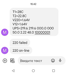
Now the module sends me messages like this:
And here is the promised source link in GITHUB.
https://github.com/lesha108/sim800_ups_monitor