People's capacity meter for batteries and accumulators BatteryTest
I have developed a cheap, accurate and extremely easy-to-use device that can be used to measure the capacity of almost any battery or accumulator (from microscopic batteries for hearing aids to lead-acid batteries). Anyone can replicate my device.
With the help of my device, everyone can test any batteries or accumulators and compare them with each other. In addition, the device will help companies choosing a battery supplier and not trusting testing laboratories.
Perhaps you have a question, why develop a new device, because on sale you can find many devices for measuring the capacity of batteries. Unfortunately, they are all either very expensive, or inaccurate, or not universal, or inconvenient. I tried to make a simple, cheap, universal and accurate device.
Main parameters of the People's BatteryTest meter:
— measuring the capacity of any batteries and accumulators (AA, AAA, CR2032, LR44, Krona, 18650 and others);
– a constant resistor as a load (this is simpler and more accurate than an electronic load);
— load current from 1 to 800 mA (depending on the value of the replaceable resistor);
— battery or accumulator voltage from 1 to 15 volts;
— test time from 10 seconds to 1000 hours (about 42 days);
— measured energy from 1 to 99999 mWh;
— measured capacity from 1 to 99999 mAh;
— constant display of voltage, current, capacity (mAh), energy (mWh) and time on the screen;
— automatic detection of test end voltage depending on the type of battery;
— transfer of testing data to a computer (you can save them and build discharge graphs);
— endless display of results after the test is completed;
— complete absence of controls.
Voltage and current are measured using a module based on a Texas Instruments INA226 chip.
During the test, the battery or accumulator is completely discharged, so the tested batteries will have to be disposed of.
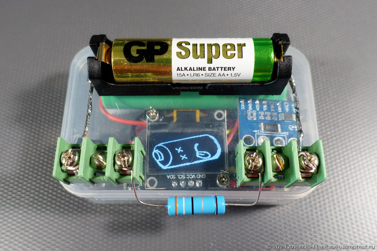
When you turn on the device, a splash screen appears on the screen, the version number and a reminder to connect the load resistor and battery or accumulator. As soon as the resistor is connected and the battery is installed in the holder, the end-of-discharge voltage and calibration parameters for the voltage and current sensor will be displayed on the screen.

After three seconds, the device will switch to the testing information display mode: the test time is on top, the current voltage and current are on the left side of the screen, and the currently supplied energy in mWh and charge in mAh are on the right side of the screen. When the test is finished, the device will show a dead battery on the screen, then its image will be replaced by the results: test time, energy released and capacity.

During the test, every 5 seconds data is transferred to the computer via a USB cable and a virtual COM port (baud rate 74880, this is exactly the speed needed so that the ESP8266’s non-disabled debugging information is not output in cryptic ways).

This data can be saved and used to create a discharge graph, for example using Excel.

There are two contact blocks installed on the device body. A load resistor is connected to the central contacts. To test some common batteries, the following resistor values are used:
12 Ohm – test the maximum capacity of AA and AAA batteries (75-130 mA);
3.9 Ohm – test of AA batteries with increased load (230-410 mA);
5.1 Ohm – test of AAA batteries with increased load (176-310 mA), test of NiMh batteries (176-235 mA);
230 Ohm – Krona battery test (23-42 mA);
1 kOhm – test CR2032 batteries (2-3 mA).
A replaceable battery holder is connected to the outer contacts. The holder for CR2032 is also suitable for small button batteries.

In the program running in the device, I tried to take into account all the nuances and emergency situations: if the voltage and current measurement module is missing or fails, the message “No INA226” will appear on the screen,
if the battery is connected, but the load resistor is not, the message “Connect the load resistor” will appear on the screen; if within an hour after turning on the device, the battery and resistor are not installed, the device will report “Long downtime. Restart.” If the battery voltage is higher than permissible, the message “Voltage above 15 volts” will appear. If the test time exceeds the limit, “>1000 hours” will appear instead of the time. After 1 minute 45 seconds of displaying the measurement result, the screen brightness is reduced to protect the OLED screen from burn-in.
The device uses inexpensive components: a cheap D1 mini microcontroller based on ESP8266, a 0.96″ OLED screen, a ready-made INA226 module. The device can be powered from a computer via a USB cable or from any 5-volt power adapter with a USB connector, as well as from some power banks, capable of not turning off with low consumption (when powered at 5V via the USB connector, the device consumes 27 mA).
I called the device popular because anyone who can solder a dozen wires can replicate it. The connection diagram of the three main modules and terminal blocks is very simple.
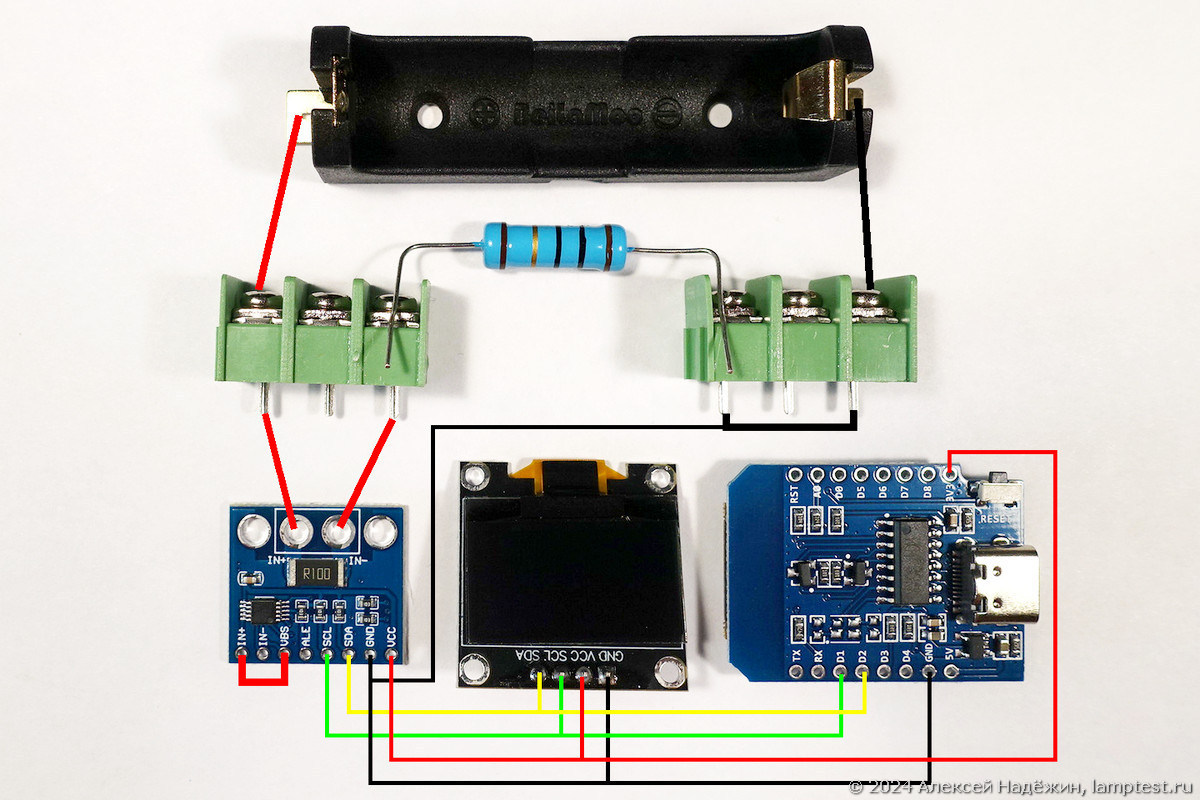
I posted the firmware, source code of the program and links to all the parts for assembling the device on the project page https://ammo1.ru/btest.
For convenience, the screen is installed upside down, with the contacts facing down (in the program the screen is upside down, if you wish, you can install the screen as usual and remove two lines from the program that turn the screen upside down).
The INA226 module is installed as close as possible to the positive terminal block.
If desired, you can install in the device an 18650 battery, a charging and protection board, as well as a voltage converter that provides 3.3 V output (its output is connected to the 3.3 V power line, to which the power contacts of the screen and the INA226 module are connected) and a switch between the positive contact battery and converter input.

A 2600 mAh battery will last approximately 50-90 hours of operation of the device (operating time depends on the type of voltage converter and its efficiency).
Some nuances for those who want to assemble the same device.
You can use INA226 or INA231 modules (this module is twice as expensive, it has a better printed circuit board layout, and there are noise-smoothing capacitors in the current measurement line).
Unfortunately, on Aliexpress you can find bad INA226 and INA231 modules, which contain rejected or counterfeit microcircuits in which the internal reference voltage source does not work correctly, which is why the voltage and current are measured with a large error. For normal modules, the voltage deviation should not exceed two digits in the third decimal place (0.999 V – 1.001 V when measuring a voltage of 1 V). I added the ability to adjust the voltage in the program so that you can use defective modules, but it is better to order known good ones.
The accuracy of current measurement depends on the accuracy of the 0.1 Ohm shunt resistor installed in the module. It is advisable to calculate the current calibration value (calibrI in the program) using a good multimeter.
The finished firmware is made for the D1 mini microcontroller. You can use any version with Micro USB or Type C connector. I recommend using D1 MINI V4.0.0 as it is the cheapest and has mounting holes.
You can use any other microcontroller board (for example, NodeMCU or Arduino Nano), just compile the program for your controller and if it does not have Wi-Fi, remove the commands that disable it.
Load resistors must have a large power reserve so that they do not heat up during testing.
I do not recommend using cheap pads (holders) for batteries with red wires – due to the poor quality of contacts and wires, they can have such a high resistance that this will significantly distort the results.
This is the first debugged and operational version of the device. In the future I want to add the following features:
— convenient calibration of the device for voltage and current using two buttons hidden inside the case;
— displaying the battery charge level on the screen if available;
— saving testing data to an SD card;
— transmission of testing data via Wi-Fi.
If you want to join the development, I will be glad.
In addition, it is planned to create a multi-channel version of the device for simultaneous testing of several batteries or accumulators.
For those who want to get a ready-made device or repeat it, I will try to make two options: a ready-made calibrated device and a kit for self-assembly with a stitched and calibrated controller.
If there are enthusiasts who are ready to test batteries and accumulators using this device, we will think about making a section with popular results on batterytest.ru, and of course, I am ready to provide such enthusiasts with the devices for free.
© 2024, Alexey Nadezhin