“Leash” for Bosch boiler or DIY Opentherm boiler regulator (not incl.

We figured out the software and it already looks like a plan, but the boiler has a hardware interface that works with voltages up to 15V, and this is not the norm for ESP, which has a 3.3V supply. A matching device is required. At least two versions of such a solution and device are already available on the Internet. I chose one that is built on a single transistor, but once again did not buy or order from Mars and soldered it myself.

Schematic image source from library and adapter project by Igor Melnik.
Further, as they wrote in the last century in the Radio magazine, “a properly assembled device does not need adjustment and adjustment,” so I spent a day adjusting it. And the story of everyday life … I came to the store and asked for the right transistor. I was told there is no such thing, I picked up an analogue on the Internet right at the checkout – KT3107 and they sold it to me in a bag. After half a day of agony, I was on the verge of deducing that it was not working, but suddenly I noticed that they had sold me another transistor. Joyful that he found the reason, he got into the Internet, but bitterly realized that he was a complete analogue in terms of characteristics. Another half a day of torment and I noticed that he is not a complete analogue in the pinout (hand-face). As a result – … does not need.
Great, the controller is flashed and configured by pins.
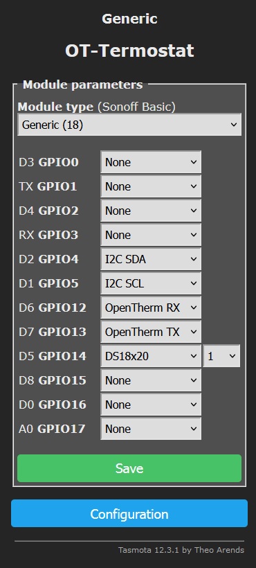
I specifically left the name of the author of the firmware Theo Arends, who made the process of using ESP controllers available to “households”.
We connect to the boiler to special terminals instead of the installed jumper. Polarity is not important. It is important to understand that removing the jumper turns off the heating, therefore, for the time the board is turned off for debugging / flashing, it is enough to close the wires taken out of the boiler again, and the boiler will continue to operate in the min / max coolant temperature position control mode.

Here is my Frankenstein.

If all steps are completed without errors, then in the console of the Tasmota web interface, at startup, we see an exchange with the boiler. Do not be afraid of a message like “OT19 command unknown.” The OT library at initialization sends several commands to check their support by the boiler. With three failures, it marks them as not supported.
To make sure that everything works, you can directly command the boiler from the console:
ot_ch 1 turn on the heating control;
ot_tboiler=60 set the temperature of the coolant;
ot_dhw 1 turn on hot water control;
ot_twater=45 set the hot water temperature.
If these commands work out, go to the next step, if not, then as in the Radio magazine …
Then the magic begins, for which, apparently, regulator manufacturers are asking for 20 sput, because everything that we have done or bought before does not cost more than 1000 rubles.
We are writing the mathematics of the PID controller.
dT = (Desired – Tin the room actual)
Tcumulative = Tcumulative previous + K integral * dT * dt
Tproportionality = Kproportionality * dT
Tcoolant = Tproportionality + Tstorage
dt = time difference between adjacent measurements, for example, if once per second, then it is equal to 1, in fact, it can be neglected, in case of equal calculation intervals. Then I did just that.
Explain how this regulator works.
At the start, when the mismatch error between the setpoint and the actual temperature of the controlled parameter (air) is maximum, the boiler is affected by the calculation of T proportionality, and the accumulative one is in the region of 0. Gradually, the effect on the boiler leads to a change in the air temperature towards the setpoint. The error decreases and T proportionality tends to 0. At this time, T accumulative has already accumulated the required value for influencing the boiler, and its growth stops due to dT = 0. The system has found its balance and further fluctuations become insignificant. The boiler operates in an economical mode, replenishing only heat leaks from the house. Anyone who drives a car knows the dependence of fuel consumption on the nature of driving.
K proportionality = 40; It has a physical meaning – this is the ratio between the ranges of the measured parameter and the impact. In my case, the spread of temperatures in the room is taken as 22.5–23.5 = 1 degree, and the spread of effects on the coolant is 80–40 = 40 degrees. Accordingly, the ranges are related as 40 to 1.
Kintegral = 0.02; This parameter also makes sense – it compensates for the static error, and the constant dt is taken into account in its value. If this parameter did not exist, then under certain conditions we would not be able to achieve the required value, as in the problem “whether a frog will come to the finish line, the jump length of which is halved with each next jump”. It is clear that there are conditions under which the frog can finish with the first jump, which means that the answer depends on its length. We have this jump 40 * 1 (dT) and tend to 0 as we approach. The initial calculation of Ki can be made from the initial parameters. For example, we assume that the house will warm up by 1 degree in two hours, respectively, we will make 2 * 60 * 60 seconds of measurements and calculations. Accumulative will be accumulated in an arithmetic progression as Ki * dT, where dT is from 1 to 0. The sum of the members of the progression will be as the product of the value of the average member of the progression by the number of its members. It turns out that we will accumulate 3600, and it is desirable for us to remain in the average value of the boiler’s capabilities, for example, the coolant temperature is 60 degrees. I remind you that at the end, the entire weight of the calculation of the coolant setting falls on Taccumulative, which means we need to reduce the accumulation rate in Ki = 60/3600 = 0.016 times.
As for weather regulation, my personal opinion is marketing. When the power of the heating system is matched to the heat losses of the house, the regulation of the air temperature in the room is supported by the same principle of influence on the boiler. For systems with a weak heating system, the issue is partially solved by predicting heat loss by lowering the temperature outside. In this solution, you just need to adjust the slope of the PI controller, namely K proportionality 70, K integral 0.04. This is undoubtedly a characteristic of your home and the figures are indicative, so manufacturers offer several curves, that is, you can have several such pairs (normal mode, medium and forced). But, don’t go to a fortuneteller, if the power is inconsistent, everything will rest against the ceiling of the boiler 75–80 degrees of coolant.
We have considered the theory, we proceed to practice. Tasmota has a mechanism for performing actions on events, implemented through rules entered into the console. You can just paste this text. Better each rule (rule) separately.
Rule1
ON System#Init DO Backlog Mem1=40; Mem2=0.02; Mem3=40; Mem4=77; Mem5=22.5; Mem6=45 ENDON
ON System#Init DO Var1=Mem7 ENDON
ON System#Init DO displaytext [zds1l1c1pp19] Tnow Tset  ENDON
ON System#Boot DO ot_ch 1 ENDON
ON System#Boot DO ot_dhw 1 ENDON
ON System#Boot DO ot_twater 45 ENDON
ON System#Boot DO RuleTimer1 10 ENDON
ON mqtt#connected DO Subscribe TempHumid, tele/WIFi-TermHumid/SENSOR, AM2301.Temperature ENDON
ON mqtt#connected DO publish tele/%topic%/SetTemp %mem5% ENDON
ON mqtt#connected DO publish tele/%topic%/Var11 %Var11% ENDON
ON mqtt#connected DO publish tele/%topic%/Var1 %Var1% ENDON

Rule2
ON event#TempHumid DO backlog Var10=%value%; RuleTimer1 10; Var11=1; event Calc ENDON
ON DS18B20#TEMPERATURE DO Var2=%value%-4 ENDON
ON Rules#Timer=1 DO backlog RuleTimer1 10; Var10=Var2; Var11=2; event Calc ENDON
ON event#Calc DO Var1=Var1+(Mem5-Var10)Mem2Var11 ENDON
ON event#Calc DO Var4=(Mem5-Var10)*Mem1 ENDON
ON event#Calc DO Var3=Var4+Var1 ENDON
ON Var3#State<40 DO Var3=40 ENDON
ON Var3#State>80 DO Var3=80 ENDON
ON Var3#State DO displaytext [ds1l2c1pp5] %Var10% ENDON
ON Var3#State DO displaytext [ds1l2c7pp5] %Mem5% ENDON
ON Var3#State DO displaytext [ds1l3c1pp5] %Var3% ENDON
ON Var3#State DO displaytext [ds1l4c1pp5] %Var4% ENDON
ON Var3#State DO displaytext [ds1l4c7pp7] %Var1% ENDON
ON Var3#State DO displaytext [ds1l5c1tS] %uptime% ENDON
ON Var3#State DO ot_tboiler %Var3% ENDON
ON mem5#State DO publish tele/%topic%/SetTemp %mem5% ENDON
ON Time#Minute|10 DO publish tele/%topic%/Var11 %Var11% ENDON
ON Time#Minute|10 DO publish tele/%topic%/Var1 %Var1% ENDON
ON Time#Minute|10 DO Mem7=Var1 ENDON
Rule1 grouped events and actions performed at startup and emergency situations. In Rule2 directly, what is done in the calculation loop. The rules won’t work right away. They must be enabled with console commands by typing Rule1 1 input and Rule2 1 input. By parameters: mem are stored in flash, var are lost on reboot.
mem1 — To proportionality
mem2 — K integral
mem3 – Minimum temperature of the coolant
mem4 – The maximum temperature of the coolant (it is important that it cannot be more than the one entered from the boiler panel)
mem5 – room air temperature set point
mem6 – hot water temperature set point
mem7 – saving Tcumulative to flash every 10 minutes in case of an abnormal restart.
var1 – Accumulative
var2 — Temperature measured by local sensor
var3 – Calculated coolant temperature and sent to the boiler
var4 — T proportionality
var10 – Temperature received from any sensor via MQTT
var11 – Flag of the sensor used: 2-local, 1-MQTT
The rules have redundancy, but even if you don’t have an MQTT sensor or display, they will still work. For the first 10 seconds, the temperature will be expected to arrive from MQTT. If it is not received within 10 seconds, then the thermometer connected directly to the controller is included in the calculation. Next comes the calculation, rationing, sending to the boiler and output to the display and in MQTT.
A graph of temperature changes from HomeAssistant, including the period of the night and the heating of the room through the windows during the day. The graph at the beginning shows that the remote sensor was turned off. I turned it off and carried it from room to room.

Graph of the change in the temperature of the coolant in the same period of time. It can be seen how it “sags” during the day, and “piles up” at night, allowing the “engineer” to sleep.

That’s all! Everyone is warm!