Instantly filling a sequence of selected physical memory cells
(continuing work on your processorand in the title about physical memory since everywhere the search engine is about Excell cells).
At first I thought – well, what a trifle for a processor, but then I thought – many people write about small things and even get advantages, why not write about small things if a new chip is being created.
I’ll say right away that the role of memory in this scheme is played by the SR flip-flops of the proposed FPGA, and the procedure for filling any number of chains of cells (or even one) is performed in two working cycles of the designed processor, regardless of the number of selected cells. I had to puzzle over this problem a little, and I had to understand what a managed buffer is (in this case it is for Logisim Evolution).
After I created a working circuit for the bridge cache to operate the processor in mode without a program counter, I began to design a circuit for managing the bridge cache. The bridge cache is a cache that provides instruction execution without a program counter, and allows execution only of instructions in designated memory locations. Essentially, managing the bridge cache comes down to instantly filling groups of selected cells. And in order to ensure uninterrupted operation of managed buffers in a complex circuit (many cells and many signal sources), I had to use the EXCLUSIVE OR trick.
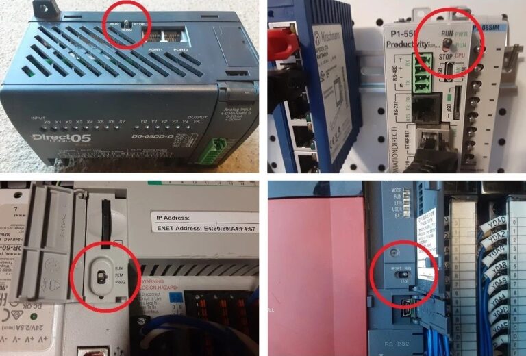
Group triggers Last – the bottom row of triggers in this image serves to designate the last trigger of this group for a specific cell, into which a unit will be written and will block the passage of the signal along the upper conductor, through which a unit is written in a row into these memory cells of the bridge cache control mechanism – into the triggers of the group Memo (an unfinished word, since in essence all this is a device for managing memory, and not memory itself).
A one signal is sent to two contacts to indicate the last cell of the circuit (in the image, the penultimate lower contact and the lower horizontal contact in the wire diagram)

Then a signal is sent to fill the memory triggers of the bridge cache management mechanism – triggers of the group Memo (the bridge cache itself is described in a previous publication and will be presented here later), and the one signal passes to the right along the circuit without hindrance, filling all triggers Memoup to the cell with a filled trigger Last . The two previously activated contacts go into inactive mode (zero signal or floating state).

And that's the trick here: the fact is that in order to give a signal to start filling the circuit, the controlled upper buffer of the previous cell must supply a floating signal to the output that does not contradict any (zero or one signal) arriving at the connection immediately after it, and the one signal must allow the signal to pass through condition for the functioning of the controlled buffer, but the one signal at the control contact will not allow the output floating signal if a zero is supplied to the input of the controlled buffer. What to do? To do this, it was decided to include an EXCLUSIVE OR element in this circuit, and when applied to the lower contact from its right, it would send a zero signal to the upper buffer, allowing a floating state at the buffer output, and then the signal from the lower right adjacent contact of the neighboring cell would go unhindered , further writing one in cells to all triggers of the group Memountil it reaches the cell with one in the group trigger Last.
Next, I attach a screenshot of a bridge cache device consisting of five cells, where the group triggers Bridges units are written accordingly (one or nal in this case are selected in the trigger FillingBridges). This circuit is asynchronous, since it is expected to be very fast (any number of cells will pass the signal unhindered, at a speed close to the speed of signal propagation along one wire; this is exactly what the entire circuit was designed to do).

It is clear that the reader is expecting something more visual, and more detailed – since I myself like to learn new things from reading interesting things, but this can still be expected in the future. For now the only way is diagrams.
In general, what remains is “surgery” on memory chips as “donors” for the command cache and “implanting” the bridge cache and its management mechanism in them, but this is more likely to happen with programming languages; you can’t get rid of it purely with circuits.