Hairdryer and bottom heating. Removal
In this article I want to show the process of removing chips in a BGA package and installing them on a new board without rolling the balls. I will describe some of the nuances that make this operation more or less painless.
A little background. A batch of devices was produced for a customer. Some of them are put into storage. After some time, a second version was developed, which turned out to be more in demand among the end user (the configuration, dimensions, interfaces and cost changed slightly). The timing of the production of a small batch coincided with the collapse of the component market. Dollar at >150. Prices for some items became simply hellish, the distributor of components with mouser fell off and for some time we were left simply without components (not counting our warehouse, which was beginning to melt before our eyes).
Nobody canceled the batch of devices and it was necessary to come up with something. The new boards contained almost all the components from the old version, which no one wanted to take anymore. The main problem was, of course, with the active and some of the connectors. There was no point in buying components at a price of x4, since the final price could scare off all customers, and selling at the old price would be a disadvantage.
We produced a batch of new boards (about 200 pieces), soldering only the passive in production. Microcircuits and connectors had to be transferred from old devices. I would like to describe the process of transferring BGA chips: DDR3 memory and iMX6ULL processor. Nowadays these components are already readily available, but back then there was simply no other option.
The iMX6ULL processor contains 289 balls with a pitch of 0.8mm and dimensions of 14x14mm (BGA289). It was also possible to solder the iMX6Q into BGA624 without reballing, but this is more difficult if you just remove it with tweezers and not with a vacuum grip.
The first stage is removing the chip from the donor board. There are several features here. Firstly, you must remove it with flux, since otherwise balls of different diameters will remain on the processor (they will be pulled out while lifting the chip). Secondly, flux must be applied on three sides of the microcircuit. If applied on all sides, an air bubble will form under the body, where there will be no flux. Thirdly, be sure to use bottom heating. Without it, the percentage of “marriage” is much higher.
I need to remove DDR and CPU. I apply flux (from a syringe) to DDR3 in a BGA96 package only on the two long sides. Processor on three sides. During heating, the flux evenly fills the entire space under the microcircuits. There is no need to press the flux under the microcircuit; a large amount of it will begin to boil and there will be a crash.

Next comes warming up. First I turn on the bottom IR heating at 400 degrees. Then I heat it on top with a hair dryer at 350-400 degrees. At higher temperatures there is a possibility of damaging the microcircuits. For example, when soldering at a temperature of 420 degrees, all USB interfaces stop working on the iMX6ULL. At lower temperatures (<350 degrees) it is not possible to achieve good removal. After the chip begins to “float” (move slightly when you press on the end with tweezers (the main thing is not to move it too much, otherwise it will jump onto a row of balls)), it must be removed with tweezers with wide ends. The more evenly you lift it, the better the balls will be preserved.
The donor board will have something like this (Fig. 2). Solder part
will definitely remain on the board, that is, the diameter of the balls on the chip will become
a little less, but this is not a problem if the passive on the new board was soldered at production.
Solder paste was also applied to the processor pads and “bumps” formed there
from solder. If the chip is installed on a clean board, it will fit
a little lower.

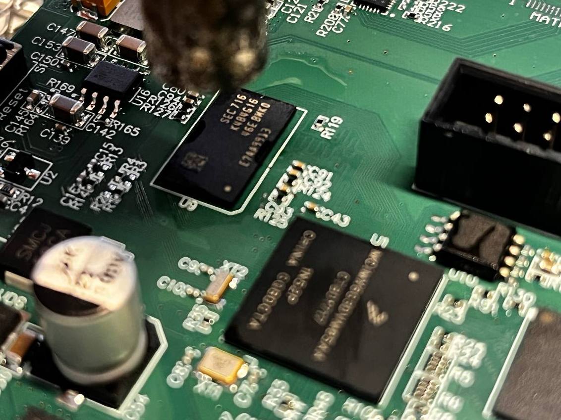
Below is an example of a new board from production. Everything is soldered, all that remains is to install the processor and memory. In the photo it seems that the amount of solder is very small, but this is not so. Here, a negative opening of the mask under the U1 chip was simply made, so the diameter of the balls looks smaller.

Memory is almost always removed well (9 out of 10), but the processor is 50/50. Let's consider a case where the film was “not very good.” It looks something like the photo below.

The right ball turned out to be larger, the left one smaller (than it should be). Most often the problem is precisely this angle, since it is not always possible to lift the tweezers vertically upward. I remove the solder from two contact pads with a soldering iron and install new balls.
There is also a small nuance here. If you simply place a ball on the contact pad, then when heated by a hairdryer, it will float and stick to the neighboring one. It will also have to be removed and so on endlessly. It is impossible to grab the ball with tweezers, since it will flatten under the influence of temperature. You just need to touch the ball with tweezers (you can dip it a little in the flux first) and it will stick.

Next, having warmed up the microcircuit, we touch the tweezers with the ball to the pad (the tweezers will be warmed up and will perform an additional heat-conducting role).
Voila! The balls are in place!

The next step is to apply flux to the new board and install the chips correctly. When a large amount of flux is applied, the microcircuits will inevitably “float” and “eat away” when heated. If there is not enough flux, it will evaporate before the solder has yet melted. It's just practice. Now the main thing is to install the chips correctly. If you try to place them right away “as needed,” that is, “ball on ball,” then when the flux is heated, the microcircuit will definitely “move off,” and according to the law of meanness, diagonally. It is necessary that the chip balls stand on the PCB itself and come into contact with the balls on the board. In this case, when heated, they will combine into one ball. The photo below shows how I place such microcircuits and how they shift while the solder is heating up.

Now everything is exactly the same, first the bottom heating, then the hair dryer on top. If everything is done correctly, the microcircuits will “go” in the directions indicated by the arrows. When the chips are in place, just as in the case of desoldering, they should move easily with tweezers.
After washing the board, look at the resulting result.

Let's see what the balls look like from the side on the DDR.

Everything seems to be fine. We check the board for a short circuit in the power supply and turn it on. We see the long-awaited bootloader.

This method is suitable for microcircuits with a relatively large pitch between balls. With eMMC, for example, in the BGA153 package everything is much sadder. It is much more difficult to both remove and install, because the pitch is only 0.5mm, and the balls are much smaller.

And finally, the main points.
When removing a BGA chip (processors, DDR4/5, etc.), apply flux only on three sides. For DDR2/3 – on two long sides.
After removing the chip, make sure that all the balls are in place and have the same diameter. If not, we restore it.
Do not remove solder (if applied) from the BGA footprint.
Apply a thin layer of flux evenly to the seat for the microcircuit.
Place the microcircuit on a cold board with a diagonal offset so that the balls of the microcircuit come into contact with the pads on the board.
First, warm up the board using the bottom heater, then heat it with a hairdryer from above.
After installation, make sure that all the balls are melted and the chip moves freely. Don't overdo it.
Before removing the board from the bottom heating station, make sure that it has cooled down sufficiently.
Clean the board from flux.
Thank you for your attention and good luck!