Four-level pulse amplitude modulation (PAM4) in DWDM systems
The dynamics of development of modern society dictate the requirements for a continuous increase in the amount of transmitted data. The total volume of global IP traffic is increasing annually. According to the Data Age report, by 2025 this figure will be 175 ZB (Zettabytes) per year. Telecom operators are faced with the challenge of comprehensive network modernization to meet growing demands.
Modern fiber-optic transmission lines have enormous throughput values. Primarily through the use of dense wavelength division multiplexing (DWDM) equipment, which allows you to combine dozens of channels for transmission over one fiber. Remember that the capacity of a DWDM system is defined as
Where
N – number of channels;
B – channel speed.
Increasing capacity is possible both by increasing the speed of each channel and by increasing their number. The frequency plan, defined by the ITU-T standard, allows you to fit up to 24 duplex channels in the C-band at an inter-channel interval of 100 GHz or up to 48 channels at an interval of 50 GHz. A further decrease in the inter-channel interval leads to the complication of the transceiver equipment. Due to the small geometric dimensions of the fiber core, the input power level becomes a critical factor. A further increase in the number of channels leads to the fact that the response of the light guide becomes nonlinear. The influence of nonlinear effects becomes a significant factor limiting the length of the regeneration section.
Increasing the channel speed is by far the most popular solution. In this regard, there is a question of replacing classic 10G DWDM solutions that no longer meet current demands. In 2010, an IEEE working group approved the international standard 802.3ba, which describes 40G/100G Ethernet. 40G DWDM solutions have not found widespread commercial use. 100G DWDM solutions are actively used in telecommunications today. First of all, we are talking about coherent CFP/CFP2 transceivers. The second solution appeared on the market relatively recently. We are talking about QSFP28 100G DWDM modules with four-level pulse amplitude modulation (PAM4). This is what we will focus on in this work.
PAM4 is one of the types of amplitude modulation (AM), in which the signal can take 4 states (Fig. 1.1). While in the RZ/NRZ formats there are only 2 states (Fig. 1.2). The figures show the same bit sequence 01101100 for two modulation formats. With the same symbol repetition period, due to the fact that two bits are encoded in one symbol, the effective transmission speed will be twice as high. For a visual representation, see Figure 1.3. shows a graph of transition states of two types of modulation.


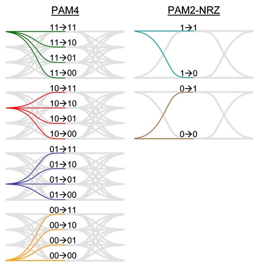
Despite the obvious advantage of PAM4 modulation, a number of difficulties must be resolved. As can be seen from Figures 1.1 and 1.2, the amplitude of the signal with four-level coding is only 0.33 of the amplitude with two-level coding. The high density of signal voltage levels leads to the fact that the signal's susceptibility to noise is noticeably reduced. Taking into account all linear and nonlinear effects, this gives an OSNR loss of approximately 10-11dB. In addition, the technological design of a transceiver with PAM4 modulation is more complex and requires a larger number of auxiliary elements, so the requirements for heat dissipation in such modules are also higher.
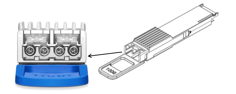
The most popular solution now is QSFP28 100G DWDM PAM4 2λ modules, operating at two DWDM wavelengths (Fig. 1.4). Two independent channels of 50 Gbit/s are formed, the signal is transmitted at adjacent frequencies (Fig. 1.5). The symbol rate of each channel is 25 Gbaud. This is 2 times less than it could be when using a QSFP28 100G DWDM PAM4 1λ module. The signal on the receiving side must have an OSNR of at least 30 dB at a power of -12 dBm, the dispersion tolerance is about 100 ps/nm. These conditions impose a limitation on the maximum transmission range. Even short distances require the installation of a tunable compensator (TDCM) with precise compensation of accumulated chromatic dispersion and erbium amplifiers (EDFA). Subject to these requirements, sufficient noise immunity of the signal is ensured for its widespread use in fiber optic lines.

Summarizing the above, we can highlight the main advantages and disadvantages of PAM4.
Advantages
Effective transmission speed is 2 times higher than with NRZ/RZ encoding
Possibility of installing modules in client equipment without transponders
The total cost of the solution is lower than when using coherent modules
Possibility of implementing a single-fiber circuit
Flaws
High requirements for OSNR
The need for high-precision chromatic dispersion compensation
High heat dissipation requirements
Let's consider a typical scheme for using 100G QSFP28 PAM4 transceivers.
Task. Organize a DWDM point-to-point topology system with a total capacity of 200G with expansion up to 400G over one fiber. Distance ~80km, attenuation ~20dB, optical fiber G652.D.
Scheme

Solution. The proposed scheme involves the use of the BZ-SH-DWB line of equipment and QSFP28 100G DWDM PAM4 2λ transceivers. The universal BZ-SH-DWB platform and a wide selection of cards allow you to implement various scenarios taking into account the client’s needs.
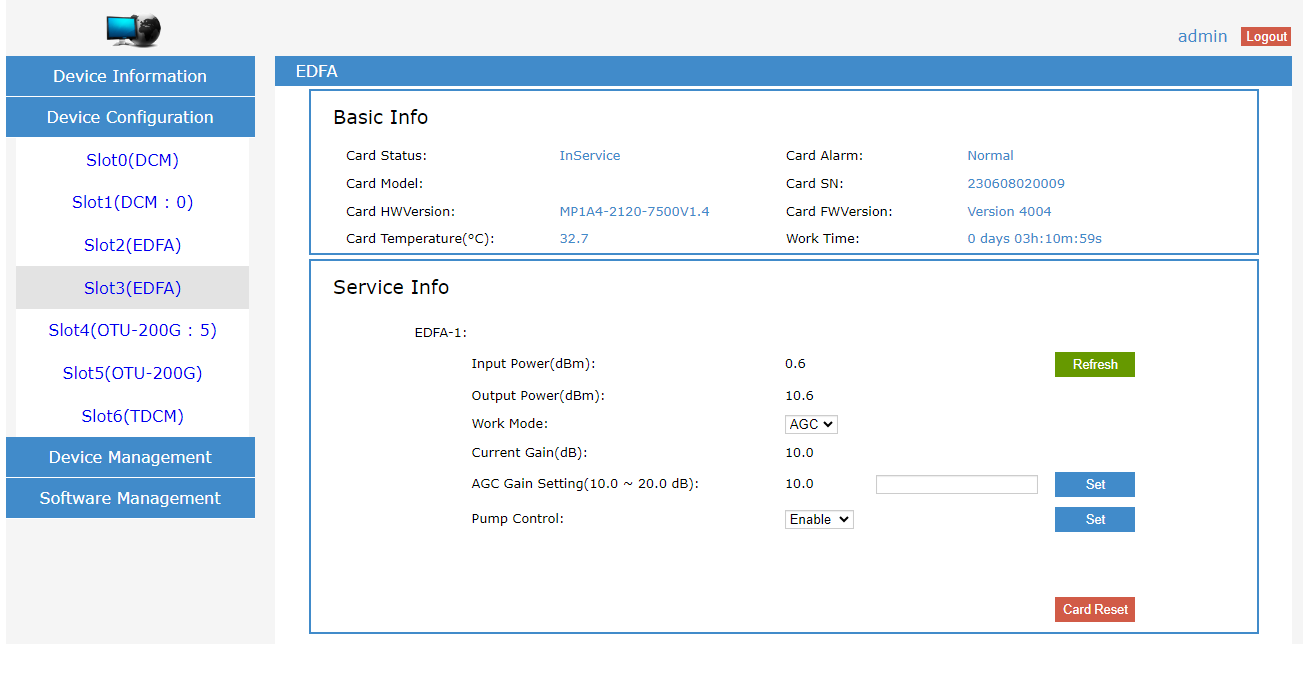
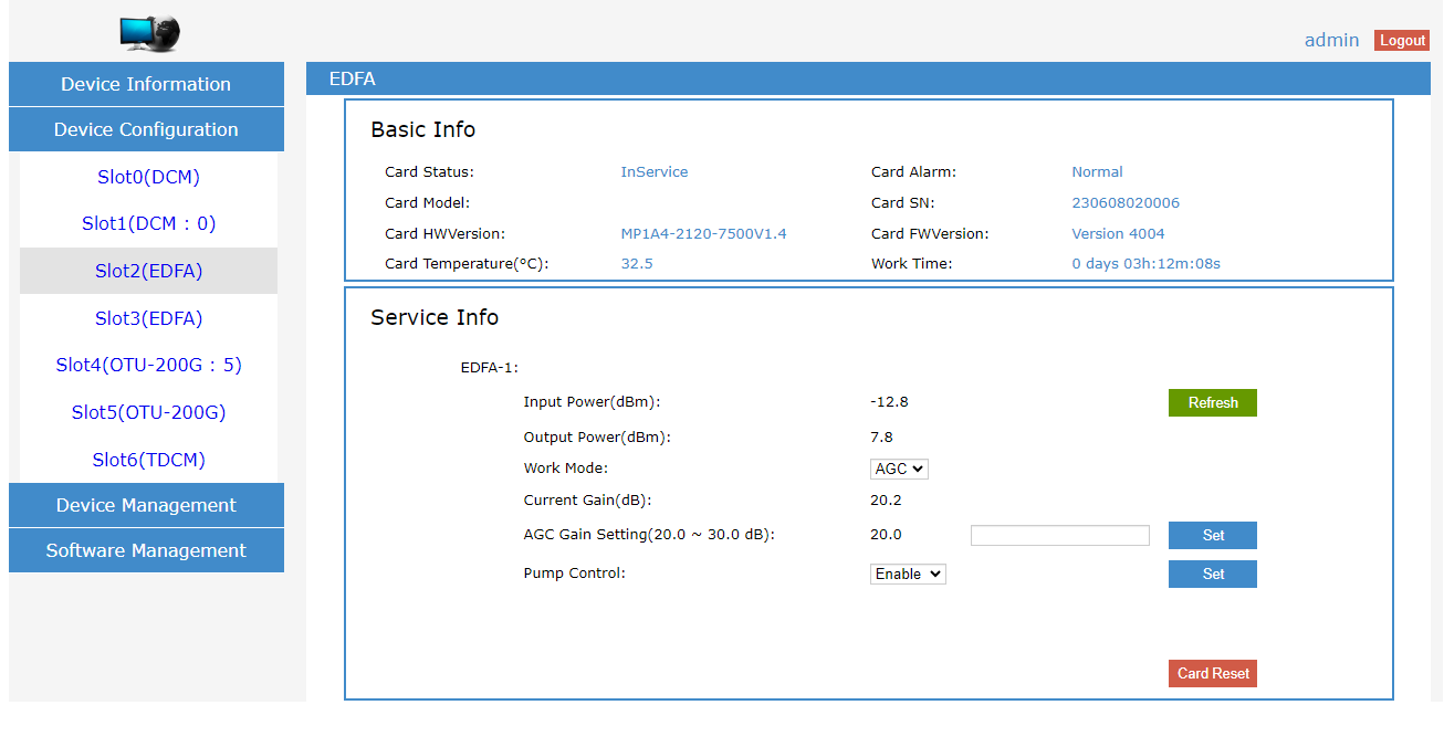
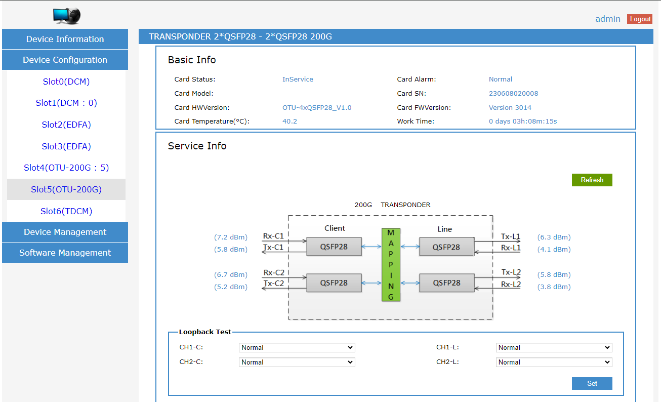
In our testing, the client equipment was Genew GS580-48S8C and Ruijie S6250-48XS8CQ switches with QSFP28 interfaces. The route consists of two laboratory reels with G652.D optical fiber, 53 km and 31 km respectively, connected to each other in a cross-connection. A fixed value dispersion compensator card (DCM) with a nominal length of 60 km is installed in front of the booster. TDCM with a tuning range of up to -1200 ps/nm is located after the preamplifier and performs additional compensation (Fig. 2.1). The device has an automatic adjustment function and is able to quickly respond to changes in line dispersion. Booster and preamplifier settings are shown in Figures 2.2 and 2.3. The amplifiers can operate in APC (output power control), AGC (gain control) modes and have a wide range of adjustment of these parameters. A transponder card with two client and two line interfaces allows you to control ports and display information about the signal status (Fig. 2.4, Fig. 2.5). The transponder has a selective error correction (SFEC) function, BER statistics are displayed in the additional information column. The second node has identical hardware configuration and settings.


Equipment list
Model | Description | Node_A | Node_B |
BZ-SH-DWB-8-2U-ST-22 | Chassis DWDM systems, 2U, 8 slots, 1*control slot, 1*fan unit 2*220VAC power supply, size 88×482×240mm | 1 | 1 |
BZ-DWB-2QS | Transponder card, PAM4, 2*QSFP28 client, 2* QSFP28 line, 100 Gb/s, 2 slots, compatible. BZ-SH-DWB | 1 | 1 |
BZ-SH-DWB-EDFA-B-20 | EDFA amplifier card DWDM Booster C-band, gain 20dB; adjustable output power/gain levels, LC/UPC, 1 slot, compatible. BZ-SH-DWB) | 1 | 1 |
BZ-SH-DWB-EDFA-P-20 | EDFA amplifier card DWDM Preamp C-band, gain 20dB; adjustable output power/gain levels, LC/UPC, 1 slot, compatible. BZ-SH-DWB) | 1 | 1 |
BZ-SH-DWB-TD-C | Tunable chromatic dispersion compensator, ±1200 ps/nm, LC/UPC, 1 slot, compatible. BZ-SH-DWB | 1 | 1 |
BZ-SH-DWB-DCM-60 | Fiber Chromatic Dispersion Compensator, -1020±3% ps/nm, LC/UPC, 2 slots, compatible. BZ-SH-DWB | 1 | 1 |
BZ-DWDM-2F-8CH-1U-LL-21-2853-60-RB | Multiplexer/demultiplexer, 2 fibers, 8 channels, 16 wavelengths 1560.61-1554.94nm-LC/UPC, 1535.04-1529.55nm-LC/UPC, COM&EXP-LC/UPC, Red&Blue filter-LC/UPC, 1RackUnit) | 1 | 1 |
BZ-QSFP28-100G-DWDM-PAM4-C21/22-CS | QSFP28 module, speed 100Gb, 192.10/192.20 THz, 1560.61/1559.79 nm, 12dB, 2CS, DDM) | 1 | |
BZ-QSFP28-100G-DWDM-PAM4-C23/24-CS | QSFP28 module, speed 100Gb, 192.30/192.40 THz, 1558.98/1558.17 nm, 12dB, 2CS, DDM) | 1 | |
BZ-QSFP28-100G-DWDM-PAM4-C53/54-CS | QSFP28 module, speed 100Gb, 195.30/195.40 THz, 1535.04/1534.25 nm, 12dB, 2CS, DDM) | 1 | |
BZ-QSFP28-100G-DWDM-PAM4-C55/56-CS | QSFP28 module, speed 100Gb, 195.50/195.60 THz, 1533.47/1532.68 nm, 12dB, 2CS, DDM) | 1 | |
BZ-QSFP28-100G-SR4-MPO | QSFP28 module, 100Gb speed, 850nm, 100m, MPO, DDM | 4 | 4 |
Conclusion
As a result of laboratory tests, the proposed scheme was successfully tested. No packet loss is observed during traffic transmission. Currently, the equipment has been launched on the customer’s fiber-optic line. In the future, it is possible to increase the system capacity to 400G by adding a transponder card, client and line modules.
Recently, our specialists have successfully launched more than 10 similar projects using PAM4 transceivers on Basis Telecom equipment (BZ-SH-DWB and BZ-SH-DW).
