ES computer processors. Constructive
Each product within the ES computer was assigned its own code, the first digit of which determined its functional purpose:
-
0 – power system;
-
1 – computer as a whole;
-
2 – processor (moreover, very often two numbers were used for the same computer: one denoted the processor in the narrow sense of the word, and the second – the processor and other central equipment, closely connected with it, but placed in separate racks – main memory, channels I / O, power supply system; in this case, each of these products had its own number);
-
3 – main memory;
-
4 – input-output channels (they were allocated as a separate device only in some machines, in others, including the EC-1020, they formed a single whole with the processor, were in the same rack with it and did not have their own number);
-
5 – drives on magnetic media and their controllers;
-
6 – input devices (usually from punched cards and punched tapes);
-
7 – output devices (on punched cards and punched tapes, on paper – printers and plotters, as well as input-output devices used as computer terminals – console typewriters, displays and printers with keyboards);
-
8 – communication equipment (modems, switches, etc.);
-
9 – data preparation devices (for example, manual punchers; they were not directly connected to the machine).
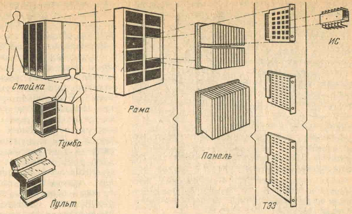
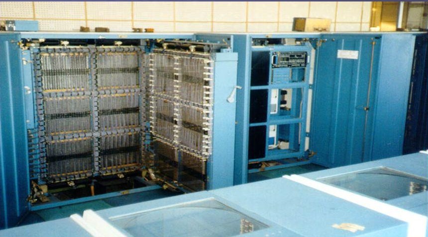
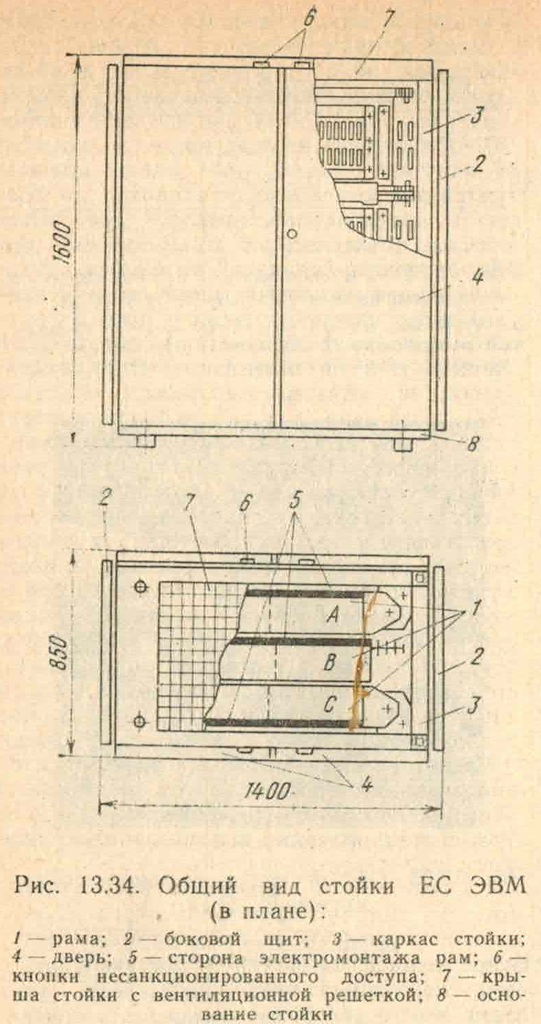
The central part (processors, memory, input-output channels and power supply systems for this equipment) of all EC computers, as well as controllers for drives on disks and tapes, until the mid-1980s, were placed in standard racks 1600 mm high, 1400 mm long and 850 mm wide. mm (standardized in GOST 25122-82, although they were already used with the first machines, that is, from the beginning of the 1970s). Typically, the processor rack was visually different from the others by the control panel hung on its front. A fair amount of other equipment had its own remotes, but they were almost always hidden behind rack doors.
Each EC computer rack generally includes three frames: a fixed central frame B and movable frames A and C, each with a typical size of 800 × 1400 × 200 mm (width, height and depth, respectively; in a particular rack, the frames could have slightly different dimensions – probably , depending on the manufacturer). The photo shows a rack, allegedly of the EC-2436 processor, with an open frame (in the foreground – disk drives).
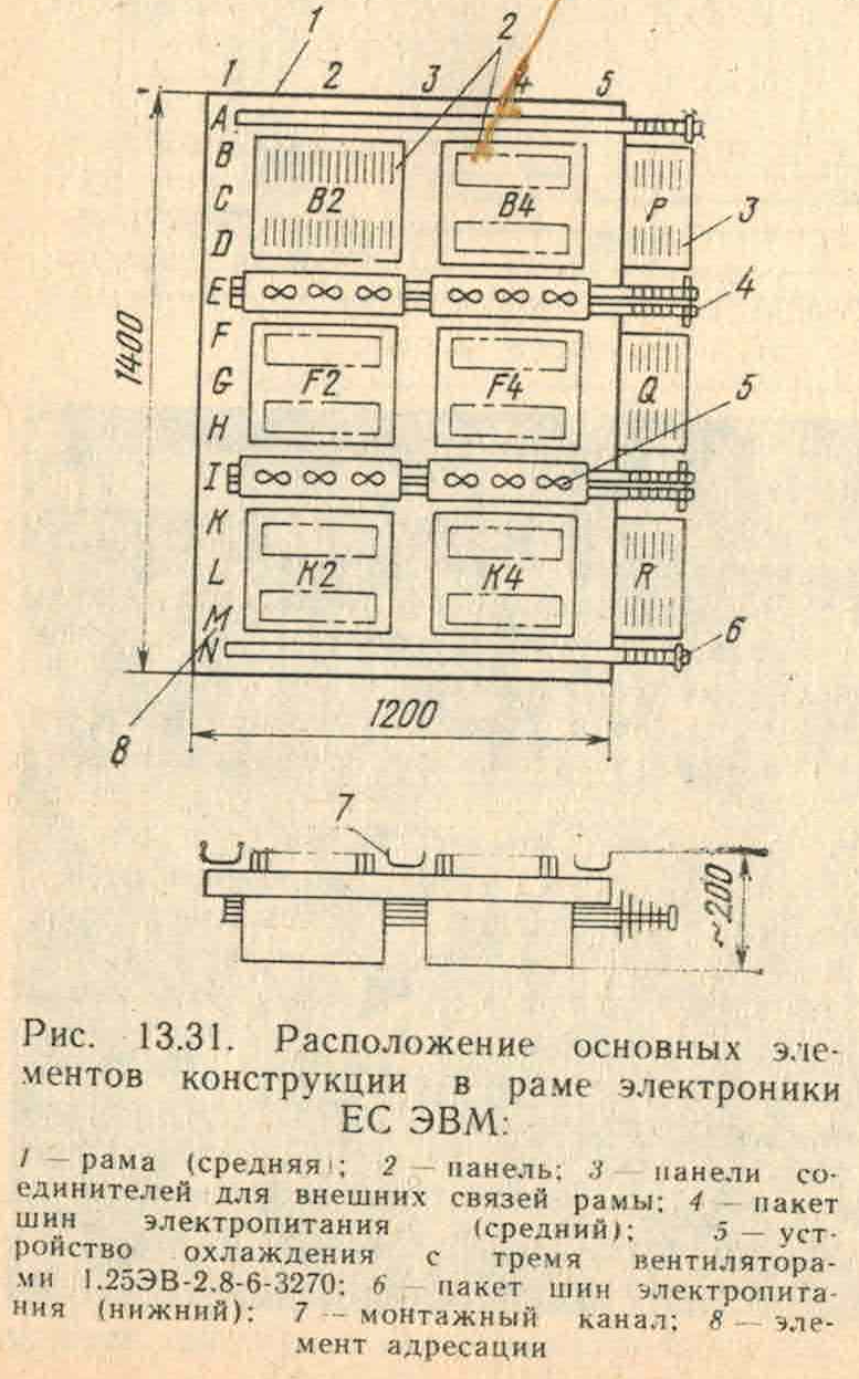
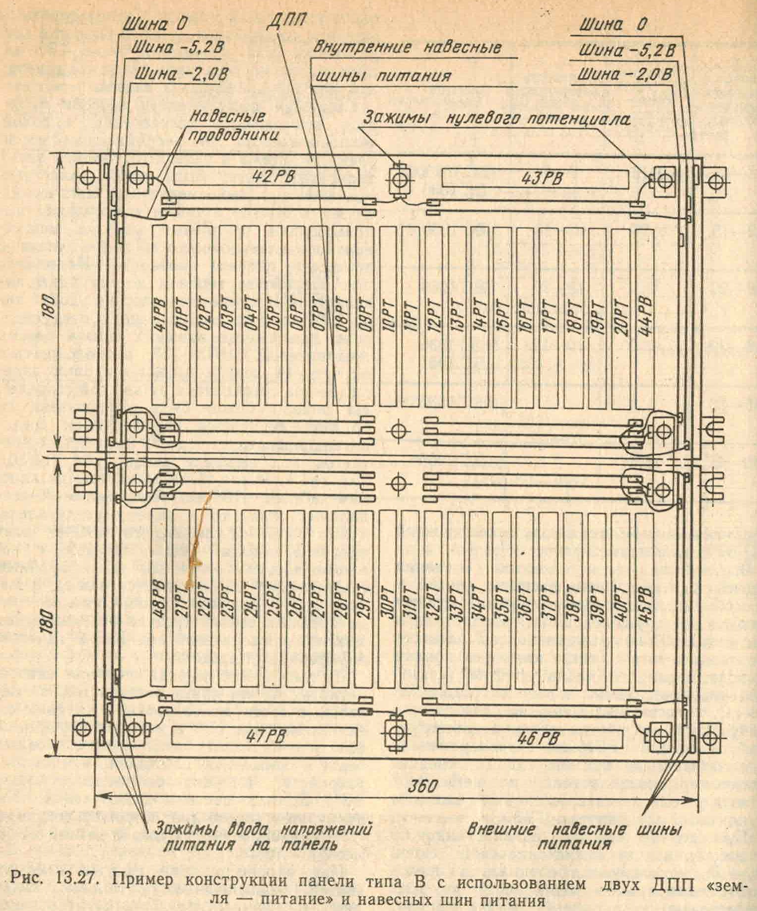
Each frame accommodates six panels measuring 360×360×200 mm (two panels in three rows). The EC-1020 and EC-1030 used the earliest panel type, designated “Type A”. On such a panel in two rows, up to 40 standard printed circuit boards can be installed in 15 mm increments – the so-called typical replacement elements (TEZ) type 1; each row of TEZs is often referred to as a half-panel. The board of the panel has the same size as the panel (360×360) and is double-sided; only land and food are diluted on it. In the EC-1050, which was developed simultaneously with the first two computers, but had the highest performance of all the machines of the first stage, “type B” panels of the same size were used, but with a multilayer panel board; this machine uses type 2 TEZs. The following two types of panels – B (EC-1035, EC-1045, EC-1060) and G (EC-1036, EC-1061) – have the same size and are used for type 3 TEZs; between themselves, they differ in the spacing of the TECs (15 and 17.5 mm, respectively; the total number of TECs in the panel remains unchanged – 40 pieces). The last two types of panels – D (EC-1065) and E (EC-1066) – have become larger (panel board size 340 × 450 mm). They returned to the step of TEZs of 15 mm, and 58 TEZs were placed on the E-type panel (on the D-type panel – 29, but they had a double height).
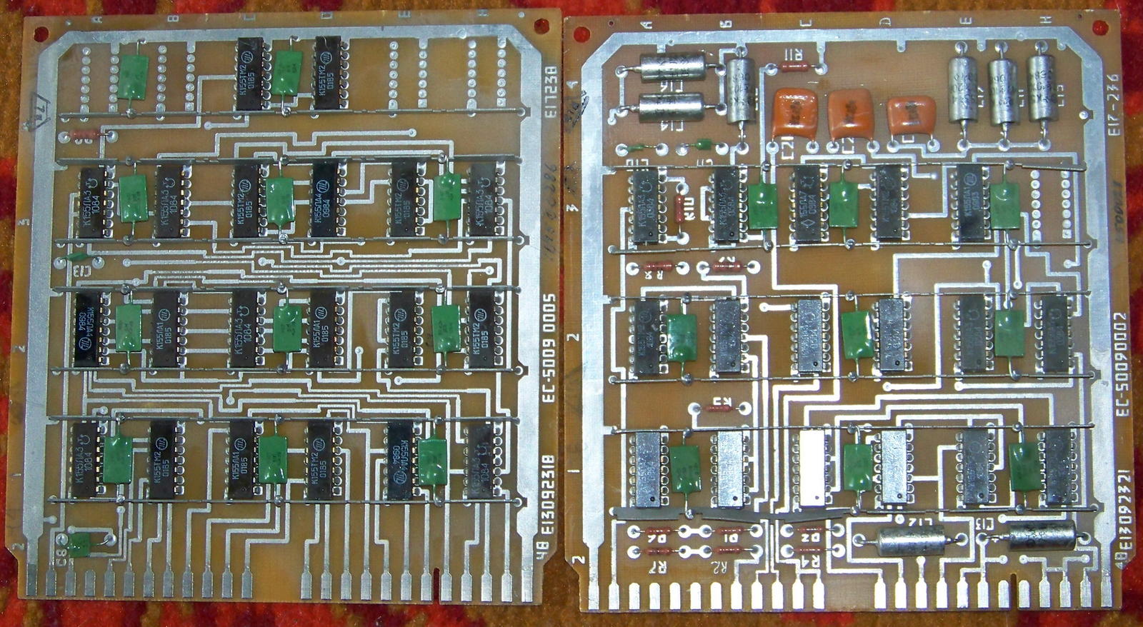
Each TEZ of type 1 (EC-1020 and EC-1030; probably also EC-1022 and possibly EC-1033) has dimensions of 140 × 150 mm (height and width, respectively; these dimensions are also preserved in TEZs of types 2, 3 and 5) and is a double-sided printed circuit board with a printed edge connector having 48 contacts with a pitch of 5 mm (the mating part, placed on the panel board, is a connector of the SNP 17 type; out of 48 contacts, 44 are signal, and the remaining 4 are designed to supply ground and nutrition). One TEZ accommodates up to 24 microcircuits in a standard 14-pin package. To supply the ground and power circuits to the microcircuits, the so-called hinged tires are used – metal strips located across the TEC at the ends of the microcircuits; filter capacitors are also soldered to these tires. Thanks to the use of mounted power rails, almost the entire area of the TEZ is free to place signal lines. Tracing of printed conductors is carried out with a step of 1.25 mm; vias are placed in 2.5 mm increments. The typical power dissipated by one TEC is 2–3 W.
As an illustration, the photo shows two different TECs from the EC-5009 device – a remote drive designed to load firmware into the central processors of the EC-1035 and EC-1036 computers. Although it was developed a couple of years after the production of the EC-1020 ceased, the type 1 TEC technology itself remained the same; they were used very widely, not only for early processors, but for all simple peripherals.
TEZ type 2, used in the EC-1050 and its modified version EC-1052, has a GRPPM7 connector and has 90 contacts (82 signal). They mainly house microcircuits of the now practically forgotten 137th series – up to 72 on one board (more about it will be discussed in the articles devoted to these machines). TEC is a 9-layer board, 4 layers are used for signal wiring. The dissipated power of one TEZ is 6–8 W.
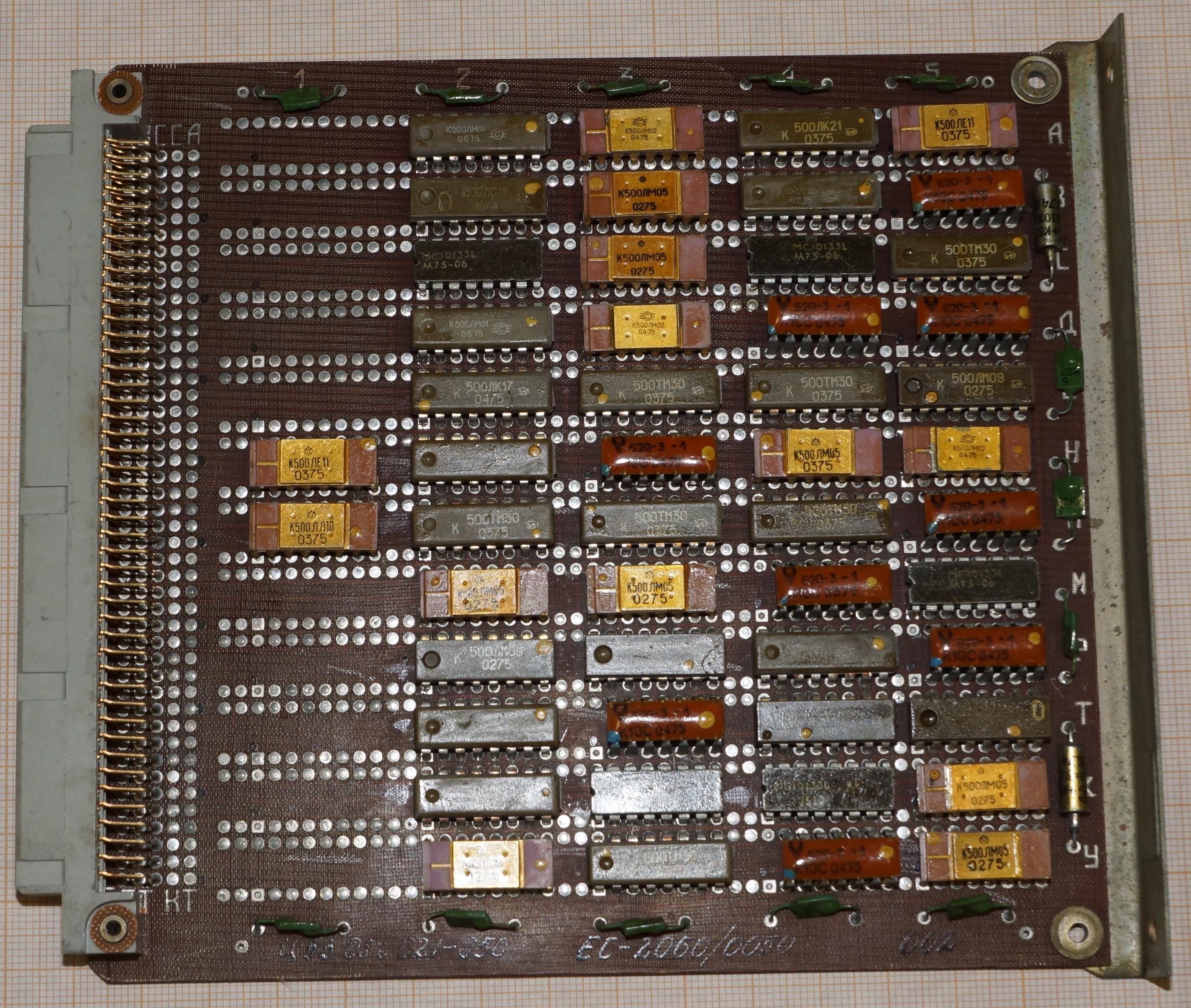
TEC type 3 is the most widespread – it is used, in particular, in EU-1035, EU-1036, EU-1045, EU-1060. It houses up to 60 16-pin microcircuits of the 500th series, interspersed with B20-4 resistor blocks (discrete resistors were used in type 2 TECs). The connection to the panel board is provided by a connector type SNP 34, which can contain up to 135 contacts, including 96 signal ones. The actual number of contacts depends on the computer; for example, in the EU-1035, if memory serves, there were 113 contacts, the rest of the connector positions were empty. TEC is an 8-layer board, there are still four signal layers. The dissipated power increased to 10–12 W.
TEC type 4 (EC-1065) differs from the others in its doubled height – it has dimensions of 330 × 150 mm and 12 layers (6 signal) and can accommodate up to 128 microcircuits. To connect to the panel, two connectors SNP 34 are used. In addition to the resistor blocks, capacitor types B18A appeared on it. Dissipated power reaches 40 watts. Remarkably, this is the only type of TEZs that uses a tracing pitch of 0.5 mm instead of the traditional 1.25 mm.
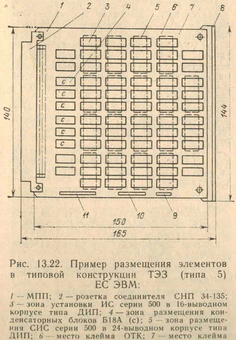
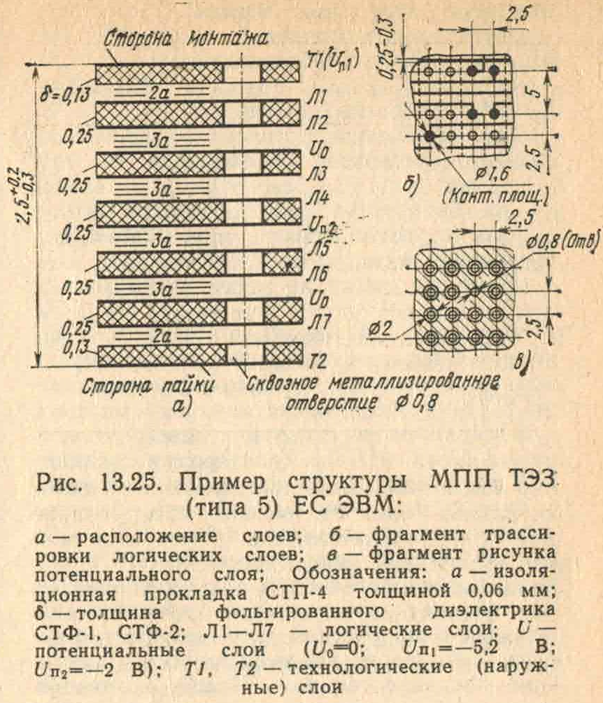
TEC type 5 (EC-1066) returned to the traditional size of 140×150 mm and is generally similar to TEC type 3, although it accommodates two more chips. Like type 4 TEC, it is 12-layer, but the number of signal layers has increased to 7. The dissipated power, however, has almost doubled compared to type 3 TECs – up to 20 W. This is explained by the fact that only the first microcircuits of the 500th series were used on machines with TEZs of the type – mainly logic elements and individual flip-flops; on TEZs of types 4 and 5, a complete, significantly wider set of the 500th series is used.
It is easy to calculate that with 100% filling of panels with TECs, and TECs with microcircuits, 5760 microcircuits can be placed on one frame. In reality, this number, of course, is less: firstly, in addition to microcircuits, it is sometimes necessary to use discrete components, and secondly, 100% occupancy is not always achieved. According to the handbook, the average efficiency of using microcircuit seats in TESs of type 1 is 0.75; in addition, not all the places of TECs on the panels are occupied, so we can roughly assume that there were about 4000 microcircuits on one frame of the EC-1020 processor, and in total there were about 9000 microcircuits in the processor (on frame B, as will be seen from what follows, there were few of them ). For comparison: on one frame of the EC-1066 processor in the same dimensions, it was theoretically possible to place 21,576 microcircuits in 16-pin packages (up to 62 microcircuits on a type 5 TEC), and the fill factor was 0.8; accordingly, in its processor there were about 50 thousand microcircuits – and not the most primitive first elements of the 155th series, but often much more complex microcircuits of the full 500th series.
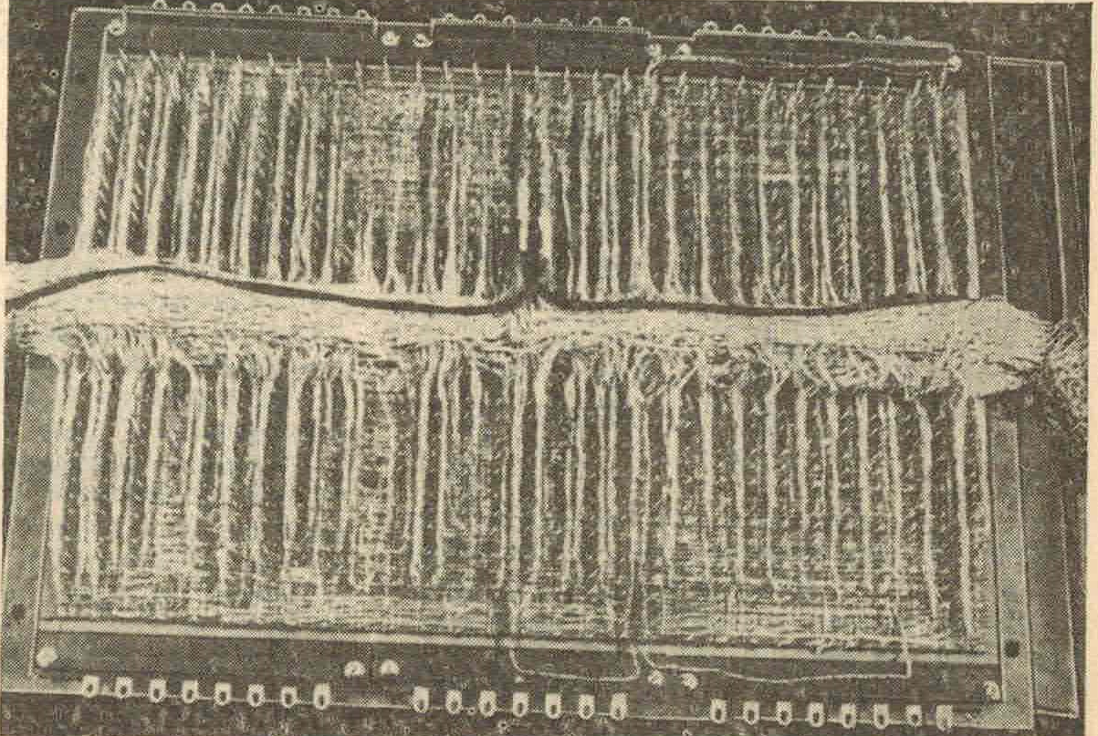
Signal connections within the panel in the EC-1020 and many other machines are made by separate wires wound onto the contacts (tails) of the connectors sticking out; The panel PCB is only used for ground and power supply. The use of a panel PCB not only for power but also for signal connections became formally possible starting with the EC-1050, but a number of later machines, such as the EC-1035, continued to use wire wrap. Perhaps it depended on the manufacturer and on the ability to produce large multilayer boards with high quality. Interpanel and interframe communications are carried out by twisted pairs (signal conductor and ground) or coaxial cables; later, flat cables were also used for this purpose. Coaxial cables are commonly used for rack-to-rack communications.
The element base for the EU-1020 and the EU-1030 being created in parallel in Yerevan were the first transistor-transistor logic (TTL) microcircuits (TTL) of the 155 series, which at that time were designated K1LB551, K1LB552, K1LB553, K1LB554, K1LB556, K1LB557, K1LR551, K1LR553 and K1LP551 (in 1975, a new microcircuit designation system was adopted, which is still used today; in accordance with it, these microcircuits became known as K155LA1, LA2, LA3, LA4, LA6, LA7, LR1, LR3 and LD1). All of them are simple logic gates (NAND, AND-OR-NOT and expander for AND-OR-NOT); I wrote about what circuitry solutions were used to create more complex standard nodes – mainly flip-flops, registers and decoders – in a separate note and I will not touch on this issue further. The features and application of other series of microcircuits will be discussed as we move on to the description of the corresponding computers, but here I note that TTL microcircuits in the ES computers are used only for processors of machines of low and partially medium productivity (the last of them is EC-1033); all other processors are built on ESL chips. In this way, ES computers are very different from SM computers, where, as far as I know, very fast, but “hot” ESL microcircuits were not used at all, but along with the usual 155th TTL series, a number of similar series were used, including TTLSh (555 and 531- I series, at least).
In addition to the listed microcircuits, discrete components and delay lines are used in special cases; their use will be discussed as needed.
The main part of the materials for this article is taken from the reference book “Application of integrated circuits in electronic computing”, ed. B. N. Faizulaeva, B. V. Tarabrina; M., “Radio and communication”, 1986.
