Electronic switch – getting rid of contact bounce
When developing a 5-output power supply, it became necessary to measure transient processes. A regular switch or mechanical relay is not suitable here because… introduces an error due to contact bounce.
When testing, you will need to turn on, turn off and periodically turn on and off the load. For the latter you will need a square pulse generator.
The following options immediately come to mind:
solid state relay
ready module
build your own
Solid state relay
The simplest solution is to get rid of the mechanical contact by using a solid-state relay. They are available for alternating and direct current. For my case, I need a DC relay.
I didn’t find anything like this at hand, and from the seller’s description it is not clear whether there is protection inside against rattling when turned on through a mechanical switch or button. This can be bypassed by controlling the relay with a generator with a long pulse duration, or by using an external circuit to suppress bounce.
To top it off, the rather high cost and the presence of a minimum switching voltage relegated this option to the background.
Ready module
AliExpress has ready-made electronic switch modules. But other than low cost and small size, they are no better than solid-state relays. There seems to be no insulation from the switched circuit, and in my case the delivery wait is several weeks. In general, I looked at a few things, added them to bookmarks and moved on to the latest version.
Build your own
The most interesting option in terms of stretching your brain and you don’t have to go anywhere if the necessary components are in your nightstand.
To get a universal device with an eye to the future, I outlined the following requirements:
state switching using a button on the board with bounce suppression;
input for connecting an external button in case of installation in another device (for example, turning on the output of a power supply);
TTL input for external control (for example for periodic switching on and off);
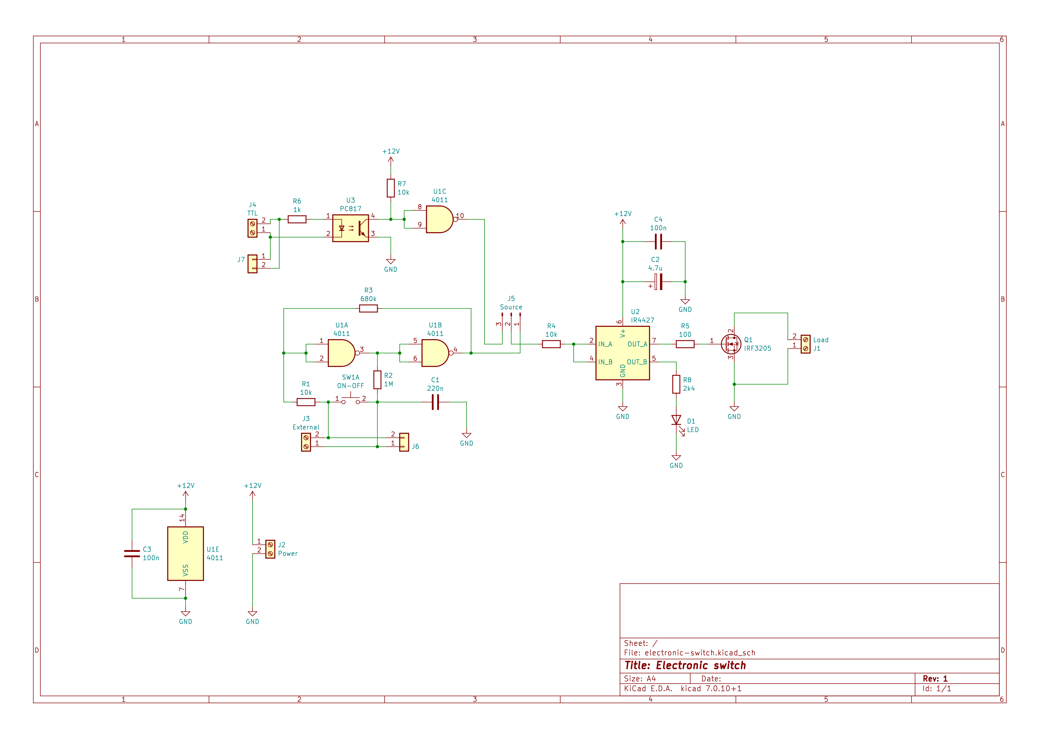
After several iterations on the breadboard, the following diagram was obtained:

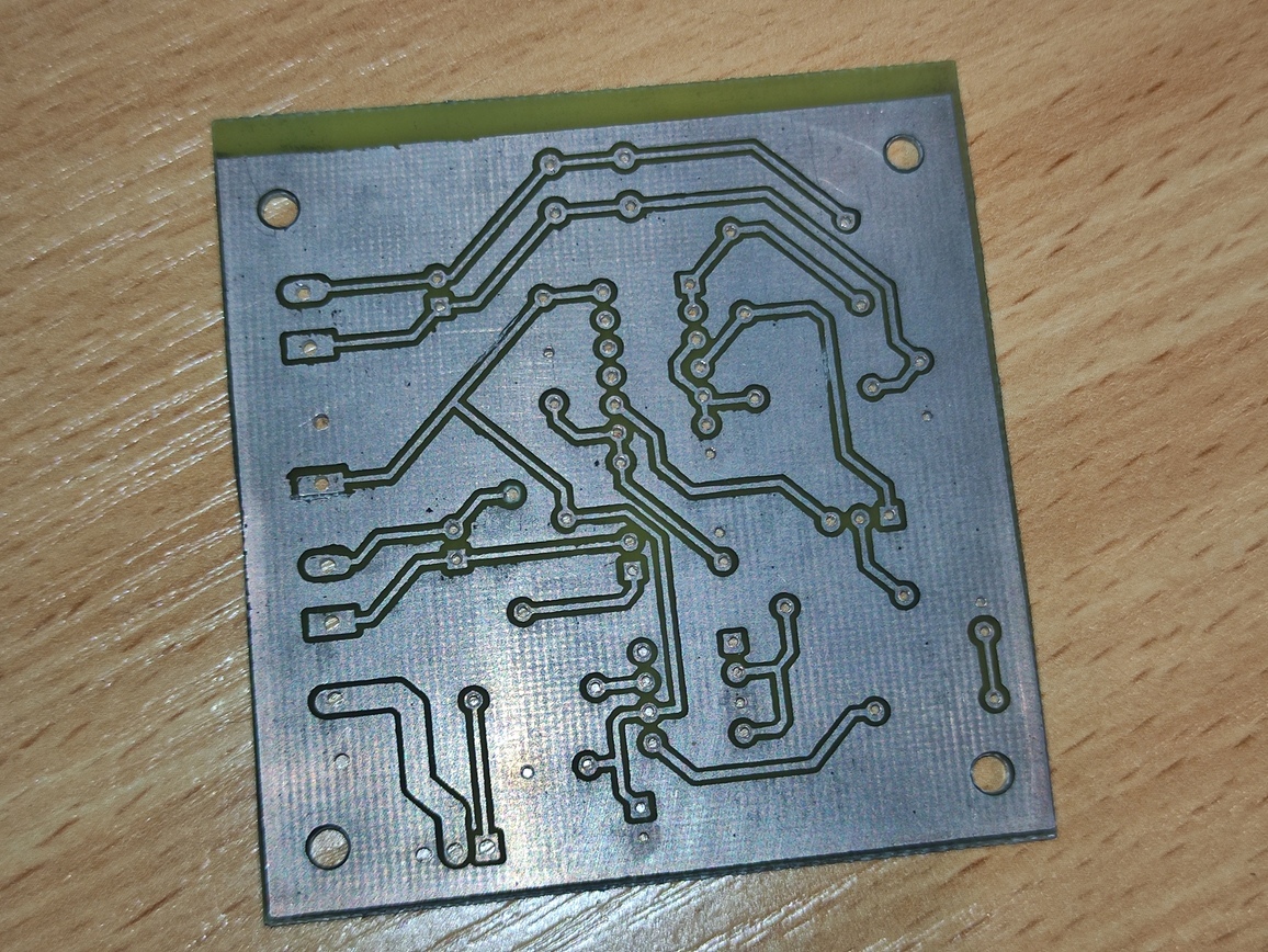
The printed circuit board was laid out in Kicad and manufactured using the LUT method. For tinning I used liquid tin from Rexant, but the impression was mixed – without flux the solder did not stick well.

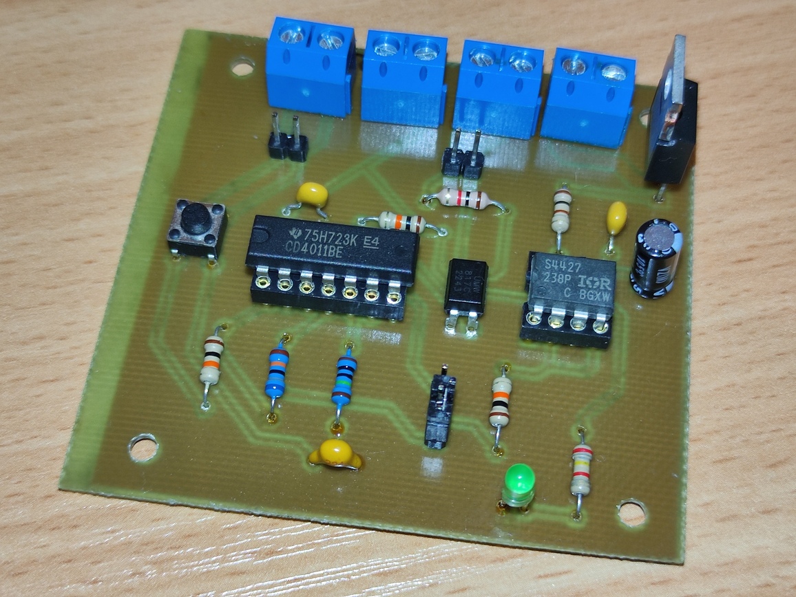
When assembled it looks like this

External button and TTL connections are available via both screw terminals and pin contacts. To switch control from a button to TTL, you need to move the jumper near the LED. The TTL input is isolated via an optocoupler and requires about 5mA from the control part to operate.
The board's power supply is from 12V to 15V (according to the documentation, the microcircuits will withstand up to 18V, but it is better to have some safety margin).

On the oscillogram, turning on the -5V output to a resistive load – there is no bounce, although the switching was a built-in button. The device turned out to be self-sufficient, although not the smallest due to the use of output components.


