casting design
Disclaimer: this is a fairly free translation of an article from protolabs.com, to which we added a little ad lib. But not just like that, but for better understanding, because the relationship between the terms “there” and “here” is a separate hellish cauldron. If you notice something is wrong (or they don’t say so), feel free to write in the comments and we’ll fix it together.
How to make a structure technologically advanced using slopes, radii, wall thickness and other solutions
Before sending plastic parts to production using injection molding, many print prototypes on 3D printers. Naturally, the features of injection molding technology are not taken into account during such printing: only the design of the product is tested, but not its suitability for manufacturing using a specific technology.
Other products are pre-manufactured using technologies close to serial production (for example, casting in silicone molds). And third customers immediately send it to production.
One thing is important: all structural elements must be develop taking into account the features of injection molding technology. Immediately design the part technologically, taking into account the presence of slopes, uniform thickness, spillability, etc.
As a reward, you will receive a close-to-ideal shape of this part and will dramatically reduce the likelihood of defects (and other problems too).
What to look for?
Slopes

Radii

Adding drafts and radii to injection molded part designs
These are not little things, but vital things. Slopes, as we said, help the part come out of the mold with less resistance at the surface: the material is compressed in the middle of the mold.
Have you regretted the degrees on the slope? Be prepared for the part to be removed from the mold under increased pressure. The possible result is damage to both the part and even the mold itself.
One good rule is to apply 1 degree of slope per 2.5 mm of its length.
Attention: sometimes this may not be enough; it all depends on the chosen material and the capabilities of the mold. What can help is design analysis for manufacturability (DFM analysis).
During the analysis process, the program takes, as it were, each element of the part’s design and considers it taking into account the specific equipment on which the part will be manufactured. This identifies parts of the part geometry where it may be necessary to increase the draft and/or wall thickness of the part.
Radii, in principle, optional. But their use can greatly simplify your life: if you smooth out sharp corners, the material will be better poured into the mold; At the same time, the strength of the part will increase.
The plastic that fills the mold cavity, like the flow of a river, flows better around fillets than corners: it flows along the path of least resistance. At the same time, the load on both the material and the form is minimized.
Radii, just like drafts, play a role in the ejection of a part: rounded corners reduce the likelihood of it getting stuck in the mold.
Wall thickness control
How you build the walls of a part determines its appearance, weight, and strength. Do you have a part with large wall thickness? Don’t be surprised if it becomes slightly deformed, and cavities and internal voids (also known as air pockets) appear on its surface. A table with recommended wall thickness depending on the material is below. But remember that this is only a general rule. It is not advisable for absolutely all parts to maintain wall thickness in the range indicated in the table.
Recommended plastic wall thickness
Material | Recommended thickness, mm |
ABS | 1.1-3.6 |
Acetal | 0.8-3 |
Acrylic | 0.6-12.7 |
Liquid crystal polymer | 0.8-3 |
Long fiber reinforced plastic | 1.9-25.4 |
Nylon | 0.8-2.9 |
Polycarbonate | 1-3.8 |
Polyester | 0.6-3.2 |
Polyethylene | 0.8-5 |
Polyphenylene sulfide (PPS) | 0.5-4.6 |
Polypropylene | 0.6-3.8 |
Polystyrene | 0.9-3.8 |
Polyurethane | 2-19 |
Wall thickness and stiffeners
The integrity of the part’s structure is ensured not only by the optimal thickness of its walls. You might think that the thicker the part, the stronger it is, but this is not true.
The design of a properly designed part must include stiffening ribs and supporting support elements (stops). They increase strength and minimize the appearance of cosmetic defects – deformation, cavities and voids.

Remove excess thickness of the part. This will allow you to maintain its height and diameter without compromising its performance. And the likelihood that you will increase her performance and improve her appearance is quite high.
Moving on: rib design. Ideally, the thickness of the ribs and walls is from 40 to 60% of the thickness of the adjacent surfaces.
The thickness of the rib emerging from the main body of the part should, ideally, be equal to approximately half the thickness of the main part. This will help reduce the likelihood of pitting and stress causing deformation: areas bOthicker ones tend to cool much more slowly than thinner ones.
To strengthen the structure and improve the appearance, it will also help you stiffening rib And stops.
And once again: smooth transitions are preferred for plastic, and a slight slope helps the material flow faster from one level to another. In turn, the stops support the walls of the part or other elements, reducing stress during molding.
Designing a part based on its position in the mold
The die and punch are often referred to as the A and B sides, or the top and bottom halves of the mold. An approach to designing parts taking into account its placement in the mold allows you to save time and money on production and improve the appearance of the product.
Let's say you're designing a simple box. By adding slopes to the outer and inner surfaces of the same half of the mold, a very deep rib is formed, the slope on the inside of which is directed towards the center, and on the outside – from the center to the sides. It is difficult to produce such a part, and the cost of equipment increases, and the walls of the box turn out to be of different thicknesses. Not only that, but the risk of damage to the mold increases when the part is pushed out of it due to difficulties in removing air to eliminate the vacuum in the deep rib.
All these problems can be minimized by using both halves of the mold. This design method requires the outer and inner walls to be parallel to each other (on both sides of the mold). This ensures constant wall thickness, maintains the integrity of the part, increases its strength and manufacturability, and reduces the overall cost of production.
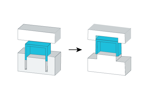
One Mold Half Approach: The walls of the box are designed as ribs. This entails higher costs for cavity machining and polishing.
Approach using both parts of the mold: design is carried out using sliders. After manufacturing, the walls of the box are “finished” by milling. This is cheaper than when the walls are designed as ribs.
Undercuts
Injection molding is a fairly fast process, so it seems that you should strive for maximum simplicity in the design of the part.
But it's not like that.
Complex part designs that require undercuts, through holes and other features can also be produced without problems.
External (lateral) undercuts are the simplest and most cost-effective, since they are made using sliders driven by an inclined column (pin). The sliders move with the mold as it opens and closes. They form the lateral undercuts. On one of the halves of the mold there are inclined columns, which, when it opens, begin to move the sliders apart. The slides move apart, the undercuts are released, and the cast part can be ejected.
If the design of the mold does not allow the use of sliders, you can take embedded elements (signs), which are subsequently removed manually.
An embed (sign) is a small form-building element of a mold that forms an undercut. The injection molding machine operator manually installs it into the mold with each pressing, and after molding, he also, by hand, removes the embedded parts from the mold and then places them back to make the next part.
Gating system and pushers
Different types of sprues and pushers are required, respectively, to correctly pour plastic resin into the mold and remove finished parts from it.
There are several ways to both fill the material and push out the part. You need to select them before making the equipment.
Most often used flat sprues (also called slotted inlet runners) because they provide mold makers with optimal processing capabilities and can be increased in size as required by the process.
Flat sprue gradually decreases in cross-section (unlike the distributing gating channels) – so that its smallest point is located on the surface of the part. This allows you to create a cooling zone between the part and the spreading sprue, that is, remove heat from the surface of the part.
Heat removal from the surface of the part is necessary to minimize the risk of cavities forming in the part. After molding, the sprue must be removed manually, leaving no more than 0.1 mm.
Tunnel sprue passes to the part at an angle through the metal of the mold; This is a funnel made at an angle. When the part is pushed out, at the thinnest point (contact with the part), the sprue cuts itself off. Point of entry tunnel sprue, despite the fact that it is on the outer surface of the part, it is located in the middle of this surface. Therefore, when using tunnel gates, there is less visible trace of them.
If you fail sprue through pusher, visible traces on outside there will be no part because the molding cavity is filled by a pusher located close to the perimeter of the part. A trace in the form of a shadow remains on the opposite side of the part due to heating and its thickness. Therefore, be careful when using this method on textured parts or those that will subsequently be polished.
Hot runner system (GKS), consisting of distribution manifolds and nozzles, operates stably: due to the constant heating of the channels, the plastic does not freeze and has excellent fluidity throughout the entire molding process. In addition, when using GCS, the amount of waste is minimal. Filling of the forming cavity occurs through the tip of the GKS injector.
Injector tip It is better to use for parts that require balanced filling – from the center to the outer edges. This minimizes any mold movement as even flat sprues can create unbalanced pressure in the mold. Hot tip sprues are probably the best from a “cosmetic” point of view (their diameter is 1.2-1.3 mm), and their marks are often hidden in recesses of various kinds or placed around a logo/text.
Straight sprues (when the channel goes directly to the part) – the most unattractive in terms of aesthetics: they have a large diameter; Accordingly, they are huge, leaving behind unsightly residues that are very inconvenient to remove (by hand, of course). But they are often used with materials containing fiberglass, or where the part is going to be refinished.