Architecture and programming Sony Playstation 1
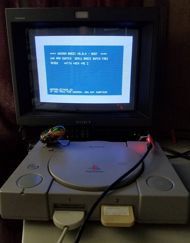
Compared to other architectures I have previously described, the architecture Sony Playstation 1 (PSX) – comparatively modern. And it’s not even about the year of release (1994) – rather, it’s a general feeling of a combination of new features and the disappearance of familiar old ones that were typical of computers and set-top boxes of the previous era.
The fact that the minimum header of a standard executable file is 2kb already speaks volumes. Such extravagance was hard to imagine in the recent past.
PSX (this abbreviation comes from the original name of the project – Playstation X) has a MIPS R3000 central processor running at 33 MHz. Moreover, Sony abandoned the coprocessor for floating point calculations and instead, the coprocessor in PSX is the so-called GTE (Geometry Transformation Engine), which performs various fixed-point operations on vectors and matrices. Other individual blocks are:
GPU (Graphics Processing Unit) – responsible for drawing primitives on the screen: triangles, rectangles, lines, etc.
SPU (Sound Processing Unit) – mainly responsible for playing samples with various post-processing.
In addition, there is also MDEC (Macroblock Decoder), which is responsible for decoding compressed (DCT + RLE) images, CDROM, DMA, interrupt controllers, various I / O ports.
The processor addresses 2MB of RAM, but neither video nor audio controllers have direct access to it. They have their own RAM, the exchange with which takes place via DMA.
The 512KB ROM contains the BIOS. It has a set of subroutines, mostly for general purposes – such as working with files, allocating memory, etc., as well as a CD Player and a shell for working with Memory Cards.
Memory cards contain 128kb NVRAM. They are designed to save and restore the state of the game, plus a BIOS vulnerability allows them to also be used to bootstrap arbitrary code.
The CD-ROM also contains its own RAM (256kb) and even the MC68HC05 processor, although you cannot load your own code into it.
The possibilities of the platform allow you to evaluate the following video:
MIPS R3000 processor
The PSX uses a MIPS R3000 microprocessor running at a clock speed of 33MHz.
This is a typical RISC processor, with all the charms inherent in RISC – both in quotes and without. The R3000 is one of the early MIPS processors (classified as MIPS I), although Mongoose-V – 12 MHz radiation-resistant microcontroller based on R3000 – flew New Horizon to Pluto not too long ago.
There is plenty of documentation on MIPS processors on the net, since they were used in many places (in Silicon Graphics computers, the PIC32 microcontroller is also MIPS, etc.), but I will still dwell on some significant points.
The processor has thirty-two 32-bit registers r0 – r31 and two registers hi, lo for use in mul/div instructions.
Depending on the assembler and the situation, the 32 registers are named r0-r31, $0-31 or $zero, $at, $v0-$v1, $a0-$a3, $t0-$t7, $s0-$s7, $t8 -$t9, $k0-$k1, $gp, $sp, $fp, $ra.
You cannot use r0 (zero) from registers for your needs – it is always zero and r31 (ra) – it stores the return address when calling the subroutine with the jal instruction (return from the subroutine is performed as jr ra).
In addition, it is better to avoid r1 (at) – it can be used by the assembler as an intermediate when translating pseudo-instructions.
There is no flag case. Accordingly, there is no need for any cmp and everything happens right in the conditional branch instruction. For example beq s0,s1,label – go to the label if s0 == s1.
Each instruction occupies 32 bits (4 bytes). Therefore, for example, loading a 32-bit constant into a register requires more than one instruction.
Since RISC processors began to spread in an era when assembly language was less and less programmed, the processor’s instruction set is not tailored for humans, but for compilers. For example, loading the number 2 into register r5 looks like this:
addiu $5, $0, 0x00000002those. add the number 2 with zero (in r0 is always zero) and put it in r5.
Even a very big fan of assembler in a few hours will hardly be able to understand what he himself meant by his own similar code. To somehow alleviate the suffering of people, there is such a thing as pseudo-instructions.
Instead of the above, you can write:
li $v0, 2when assembled, this pseudo-instruction becomes the above addiu (or ori – depends on the assembler).
Not every pseudo-instruction turns into a single processor instruction. For example, if you write:
li $v0, 0x012345678then it will turn into the following:
lui $1, 0x00001234
ori $2, $1, 0x00005678
the reason is obvious – it is problematic to compact a long constant together with an operation code into 32 bits.
Or, for example, cyclic left shift of the contents of t2 by t3 bits and placing the result in t1 is done as a pseudo-instruction:
rol $t1,$t2,$t3if you write a tiny intro, the result of assembling such a pseudo-instruction may surprise you unpleasantly:
subu $1,$0,$11
srlv $1,$10,$1
sllv $9,$10,$11
or $9,$9,$1
or, say, you wanted to subtract a number from a register and wrote:
subi $t0, $t1, 3and then you find in the resulting code:
addi $1, $0, 3
sub $8,$9,$1
(this was done by MARS)
or
addi t0,t1,-3(this was done by nvasm)
this is because there are no instructions for subtracting a constant (subi, subiu) in MIPS. If you want to subtract – add with negative numbers and don’t fool the assembler!
In short, there are many different pseudo-instructions, and their set and methods of interpretation vary from assembler to assembler. If you want to be sure of the result, it is better to sacrifice readability and avoid pseudo-instructions.
Load/delay slots
In the code for many RISC processors, you can often find a sequence of the form:
	beq	label	; или любой другой переход
	nop		; эта инструкция будет исполнена в любом случае
This is called “branch delay slot”.
Due to the peculiarities of the logic of the pipeline, the instruction following the jump instruction is always executed (i.e., it doesn’t matter if the jump occurred or not), so either nop is inserted there, or, if size optimization is important, some useful instruction.
/ joke about the jump instruction inserted right after the jump instruction /
There is also the so-called “load delay slot” when loading from memory into a register:
	lb	v0, data(t0)
	nop		; в v0 ещё ничего нет, содержимое будет доступно только следующей инструкции
There is a similar problem with mfhi/mult. It seems that somewhere in the region of MIPS R4000 – R8000 problems with load delay slots have been solved – i.e. when you try to get something from this register too early, the processor slows down and waits until the correct value appears there, after which it gives it back (although I don’t really understand how they did it with backward compatibility).
When using GTE load / store instructions, there are also delay slots – as many as two (!) Instructions. Although, here the testimony diverges – in some places they write that this is not true for any such instructions – it is very dreary to check this.
alignment
Addresses that are accessed to load a word must be 4-aligned (and 2-aligned for halfwords).
Those.:
	lw	$s0, 0x10010000	;  всё хорошо
	lw	$s0, 0x10010001	; exception

	lb	$s0, 0x10010000	;  всё хорошо
	lb	$s0, 0x10010001	;  тоже всё хорошо (потому что загружаем один байт)
Therefore, before dw, from where we are going to take the value, we must write align:
.align 4

label:
	dw	0x1234
I also advise you to google about lwl and lwr – the abyss will open up before you.
coprocessors
The MIPS R3000 can have four coprocessors.
cop0 – reserved for handling exceptions, interrupts, etc.
cop1 is usually a coprocessor for floating point calculations, but PSX saved on this – it is not.
cop2 – GTE (Geometry Transformation Engine) – see below
cop3 – missing from PSX
There are a number of instructions for working with coprocessors:
LWCn cop_reg, offset(base) – load value from memory into coprocessor n data register
SWCn cop_reg, offset(base) – save value from coprocessor data register n to memory
MTCn cpu_reg, cop_reg – write value from processor register to coprocessor data register n
MFCn cpu_reg, cop_reg – write value from coprocessor data register n to processor register
CTCn cpu_reg, cop_reg – writing the value from the processor register to the control register of the coprocessor n
CFCn cpu_reg, cop_reg – writing the value from the control register of coprocessor n to the processor register
COPn opcode – execution of opcode operation (25 bit 0..1FFFFFFh) by coprocessor n
GTE
GTE – Geometry Transformation Engine acts as a cop2 coprocessor for MIPS in PSX. In fact, this is a kind of SIMD variant – for operations on vectors and matrices (multiplication, addition, various operations with RGB, etc.). Operations are performed with a fixed point. There is no coprocessor for floating point calculations in PSX, which, by the way, are connected with specific distortions in games.
The GTE has sixty-four 32-bit registers – 32 data registers and 32 control registers.
Loading into GTE registers is done by mtc2, lwc2 and ctc2 instructions
Loading from GTE registers with mfc2 , swc2 and cfc2 instructions
The GTE instructions themselves are a cop2 instruction and 25 bits of GTE instruction code.
That is, for example, the SQR command will look like this:
cop2 0x0a00428machine code for it: 0x4aa00428
Each GTE instruction is executed in several cycles.
In the code examples for GTE (below), I use the gcc inline assembler syntax, since this is the most convenient way to view values in the debugger.
There are no clear standards for instruction mnemonics of commands associated with coprocessors and their registers – the authors of assemblers, debuggers and disassemblers give free rein to their imagination.
The general meaning is as follows:
1. You need to enable GTE (cop2). To do this, you must first write the magic number to the SR cop0 status register (otherwise, nothing related to the GTE will work – even loading into its registers):
	"li    $t0, 0x40000000;"	// 30-й разряд в единицу, загружаем константу в регистр t0 процессора
	"mtc0  $t0, $12;"	// переписываем из t0 в r12 cop0 (SR)
Those. in instructions mtc, mfc the first operand is the processor register, the second operand is the coprocessor register.
If, for some reason, you care about the rest of the bits of the status register and do not feel sorry for memory, you can make it prettier:
	"mfc0  $t0, $12;"
	"li    $t1, 0x40000000;"
	"or    $t0, $t0, $t1;"
	"mtc0  $t0, $12;"
2. Load something into GTE registers (cop2)
	"li $a0, 0x1;" // загружаем 1 в регистр a0 процессора
	"li $a1, 0x2;" // ... 2
	"li $a2, 0x3;" // ... 3

	"mtc2 $a0, $9;" // загружаем содержимое регистра a0 процессора в регистр IR1 GTE (он же r9 cop2)
	"mtc2 $a1, $10;" // ... IR2
	"mtc2 $a2, $11;" // ... IR3
	"nop;" // delay slot
	"nop;"
3. Perform the operation. In this case, it is SQR – i.e. values in registers IR1, IR2, IR3 are squared
	"cop2 0x0a00428;" // SQR
	"nop;"
	"nop;"
4. Load the result from the coprocessor registers back into the processor registers
	"mfc2 $a0, $9;" // загружаем содержимое IR1 GTE в регистр a0 процессора
	"mfc2 $a1, $10;" // ... IR2
	"mfc2 $a2, $11;" // ... IR3
	"nop;"
	"nop;"
Thus, at the output we get the numbers 1,4,9 in the registers a0, a1, a2 (squares 1, 2, 3)
And one more thing – the result in the registers IR1, IR2, IR3 is truncated (saturation) to 15 bits. Those. if the SQR input is 100, 200, 300, then the output will be 10000, 32767, 32767. To get uncut values, you need to take them from the MAC1, MAC2, MAC3 registers (r25, r26, r27 cop2). There will be 10000, 40000, 90000.
In this case, if the values are cut off, the bits corresponding to the registers in which this happened will be set in the GTE cop2r63 flags register.
I analyze this example in such detail because, despite the large number of various descriptions of registers and GTE commands, a simple example in assembler was not found and it was not immediately possible to understand how and what to do.
GPU
GPU (Graphics Processing Unit) executes commands for drawing primitives, the list of which is sent to it [обычно] via DMA from main memory. The commands must be listed in a linked display list, where for each element (command) the following are listed:
a link to the next command, or $ffffff if the command is the last one in the list
current command size (including parameters)
command code
parameters (the number depends on the specific command)
The main commands are drawing primitives. Primitives are as follows:
Filled Triangle
Filled quad (actually made up of two triangles, which affects the quality of the fill)
Straight line
Filled rectangle (draws faster than a quad)
Primitives can have either a simple color fill, a gouraud (gradient) fill, or a texture fill.
It looks something like this:
            la a0, list
            jal SendList                ; там десяток инструкций для настройки DMA

[...]

list

; треугольник, залитый цветом
poly
    db line, line>>8, line>>16, $4 ; ссылка на следующую команду и размер команды
    dw $2000ff00    ; $20 - polygon. CCBBGGRR (C - command, b,g,r - color)
    dw $00100010  ; y0=16, x0=16
    dw $00e8027f    ;  y1=232, x1=639
    dw $01e000a0   ;  y2=480, x2=160

; линия одного цвета
line
    db poly_g, poly_g>>8, poly_g>>16, $3 ; ссылка на следующую команду и размер команды
    dw $400000ff    ; $40 - линия одного цвета. CCBBGGRR (C - command, b,g,r - color)
    dw $00000000 ; y0=0, x0=0
    dw $00f0013f ; y1=240, x1=319

; треугольник с заливкой Гуро
poly_g
    db block, block>>8, block>>16, $6 ; ссылка на следующую команду и размер команды
    dw $30ff00ff    ; $30 - треугольник с заливкой Гуро. CCBBGGRR (C - command, b,g,r - color)
    dw $00300010 ; y0=48, x0=16
    dw $30ff0000    ; color 2
    dw $0028013f    ; y1=40, x1=319
    dw $300000ff    ; color 3
    dw $00f00080    ; y2=240, x2=128

; прямоугольник
block
    db $ff, $ff, $ff, $3 ; ссылка на следующую команду и размер команды
    dw $02ff0000     ; $02 - прямоугольник. CCBBGGRR (C - command, b,g,r - color)
    dw $00500050   ; y0=80, x0=80
    dw $00550060   ; y1=80, x1=96
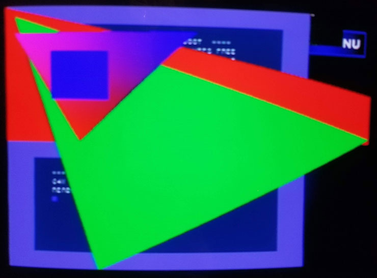
As I already mentioned, the GPU has its own 1MB of memory. It is organized as a 1024 x 512 pixel framebuffer. Each pixel is one word (16 bits).
This memory is accessed not by addresses, but by coordinates (see command parameters in the display list).
By writing to registers, you can specify exactly which part of this framebuffer should be displayed. A fairly typical approach is to allocate two pages in this framebuffer, 320×240 in size, on one of which we draw, and the second we show (the standard way to provide flicker-free output).
In this case, the rest of the frame buffer is used for textures, fonts, sprites, etc. (besides primitive commands, there are commands for moving blocks between main memory and video memory, in any combination).

By the way, the concept of “sprite” (sprite), which appears in the PSX documentation, is not a sprite in the traditional sense of the word. It’s just a rectangle with a texture.
While, as I said, 320×240 is typical, it’s not the only option. If you do not need page switching, you can use, for example, the 640×480 mode. The only thing in this case is to enable scanning with interlaced lines, otherwise a regular composite monitor will not be able to display such a resolution. Accordingly, the image will flicker noticeably.
As for colors, 15 bits (32768 colors) per pixel are displayed. The 24-bit mode, which is in the documentation, concerns only MDEC decoding of a video stream from a CD-ROM.
As for the display of 3D objects, the GPU does not know how. All this must be done manually, using polygons, using GTE for calculations. At the same time, sorting also needs to be done by yourself, taking into account the fact that each next list primitive is drawn on top of the previous one.
SPU
The main function of the SPU (Sound Processing Unit) is, in fact, playing ADPCM samples (16-bit signed) independently on each of the 24 channels with the formation of an ADSR envelope. The SPU has its own memory – a 512kb buffer into which samples are loaded via DMA from the main memory.
Setting the volume, envelope, reverb and other things is done by writing to certain RAM addresses, to which the SPU registers are mapped (they are all 16-bit).
Examples of playing samples are looked for quite easily, but as an example, I will show a rarer mode of using the SPU – noise generation. This mode does not require samples, which means it provides the smallest possible program size (in this case, about 80 bytes):
        org $80010000

        lui r27,$1F80           ; I/O base

	    li r8,$ea30	            ; 1100000100110000 enable noise (no adpcm)
        sh r8,$1DAA(r27)        ; SPU_CONTROL

        li r8,$3fff             ; master volume = 011111111111111

        sh r8,$1d80(r27)        ; master volume left
        sh r8,$1d82(r27)        ; master volume right

        li r8,$1010		        ; SPU buffer address

        sh r8,$1C06(r27)        ; set SPU buffer address

        li r8,$3fff             ; volume = 011111111111111

        sh r8,$1C00(r27)        ; volume left
        sh r8,$1C02(r27)        ; volume right

  	    li r8,$bf3f		        ; 1011111100111111
        sh r8,$1c08(r27)        ; SPU_CH_ADSR1

	    li r8,$cfff		        ; 1100111111111111
        sh r8,$1c0a(r27)        ; SPU_CH_ADSR2

	    li r8,1
        sh r8,$1d94(r27)        ; SPU_NOISE_MODE1

	    li r8,1
        sh r8,$1d88(r27)        ; SPU_KEY_ON1

	    jr ra
	    nop
For noise, frequency (in SPU_CONTROL), loudness, ADSR are indicated here. Playback is on channel 0.
I emphasize once again that the noise generation mode and the playback mode of ADPCM samples are mutually exclusive (bit in SPU_CONTROL). Not everything that works for samples will work for noise.
Ports
Parallel port – available only in older PSX models (I have it in SCHP-7502). Useful except for PSIO and all sorts of Action Replay cartridges. Well, there are some very exotic devices, such as a set-top box for viewing VCDs.
Serial port – used for multiplayer games. Through this port, you can connect two PSX with a cable. However, the games that supported it were not much. And later, in PS One, Sony removed this port as well.
Memory card – memory cards are inserted into this connector, which are designed to save the state of games. Their capacity is 128kb, although there are left Chinese ones at 64kb. Due to the vulnerability, code can be run from memory cards (see UNIROM).
Video – composite video output + sound. In some places they write that this connector supposedly also has S-Video, but this is not accurate (perhaps it depends on the PSX model).
Game pads – for connecting gamepads
Emulators
There are several emulators, of which developers are popular no$psx And pcsx-redux.
no$psx works extremely unstable for me – i.e. very many normal exe’s don’t work, moreover, on two different PCs (Win10). This is rather strange, because It seems that this emulator is considered to be completely working.
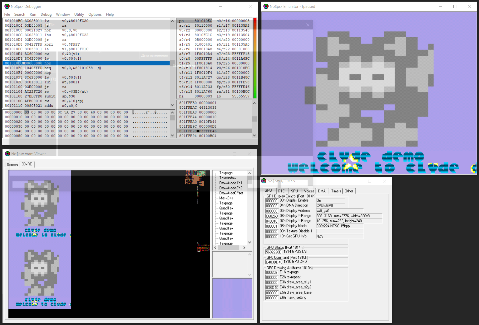
I ended up using pcsx-redux which had no problems. It also supports debugging.
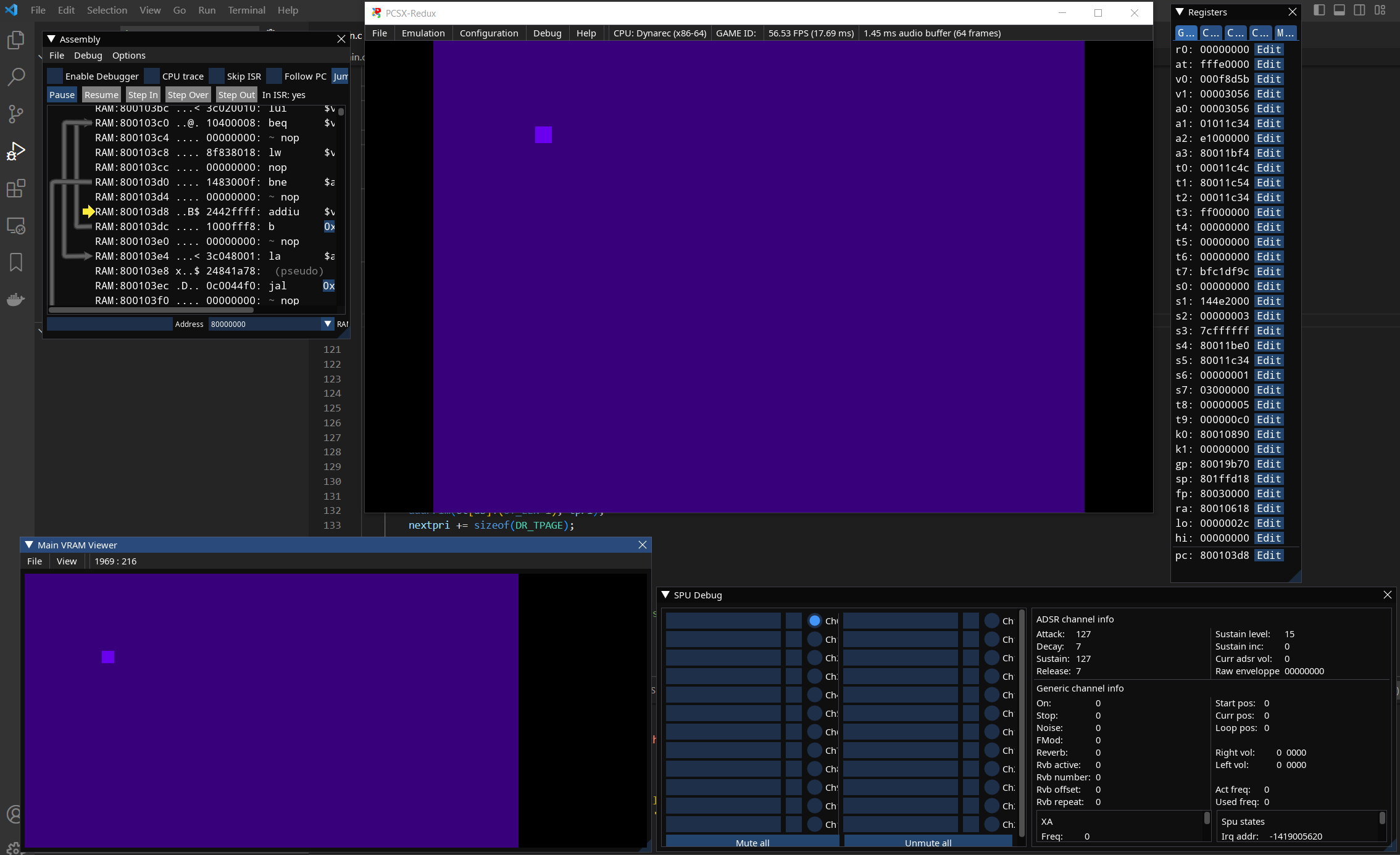
From the command line, exe files are launched like this:
pcsx-redux.exe -exe filename.exe -run
Among the popular ones, one can also mention Duckstation.
By the way, none of the emulators I know can record to a video file.
Some open bios is supplied with the emulators, so it is recommended to find and download the original bios from PSX (however, this is not necessary).
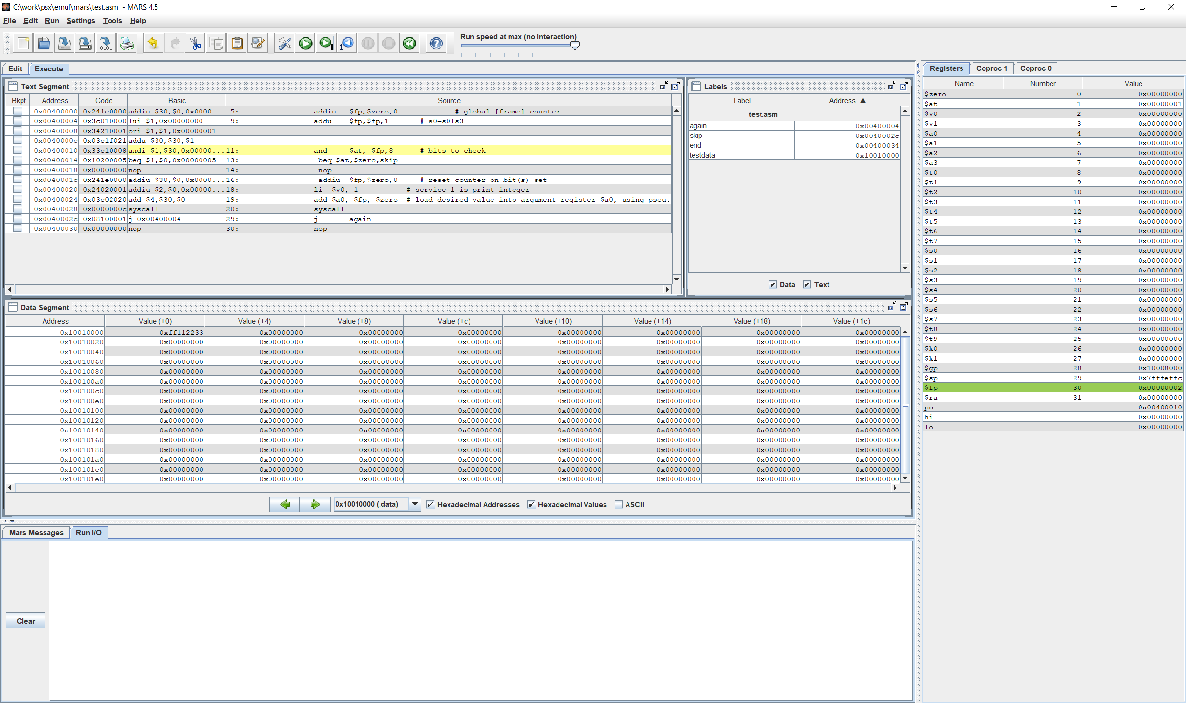
In addition, I will mention that there are several online and offline emulators of separate MIPS processors, which is useful for quickly checking code snippets and learning. I used MARS – it seemed to me the most convenient.
Development
While two developer versions of the PSX have been released, they are currently more of a collector’s item than a practical one. Now there are more modern and convenient development tools.
assembler
You can use gcc from PSn00bSDKif you like its syntax (registers starting with $ and other charms), or one of two assemblers:
nv-spasm is a modern Win10 variation on the theme spasms (exe can be found Here), which at the output gives a ready-made PSX exe, or, if you specify the appropriate parameter, a binary.
A binary without a title can be useful if you want to write a short intro, because the exe’s header adds a few kilobytes to the code.
nv-spasm has a number of problems. For example, there is a very weak preprocessor – it does not understand brackets, binary literals (% xxxx) are not supported, cop2 for some reason assembles the corresponding cop0 into an instruction, for neg s3, s3 it does not generate code at all (although logically it should be sub s3, zero,s3 ) and so on.
There is a more powerful assembler armips (for example, there are macros there), but with it you will have to make the exe from the binary separate script.
I was the first to come across nv-spasm and, having bought into the fact that it immediately generates normal PSX exe / bin, I pretty much suffered with it. I recommend not to repeat my mistake and try armips.
C
There are several SDK options, but a modern one that does not require exotics like Windows 95 / XP – in fact, only PSn00bSDK. It is a regular GCC with libraries and examples. Works under Win10 and Linux.
In the documentation ( psn00bsdk\share\psn00bsdk\doc ) everything is more or less chewed up. In short: install additional cmake, set the path to bin\ and the PSN00BSDK_LIBS variable, then take an example from psn00bsdk\share\psn00bsdk\examples and run it in its directory:
cmake -S . -B ./build -G "Ninja" -DCMAKE_TOOLCHAIN_FILE=C:/work/psx/psn00bsdk/lib/libpsn00b/cmake/sdk.cmake
cmake --build ./build
Get .exe in build/
If you need not just an exe, but a CD image, look here. psn00bsdk\share\psn00bsdk\template
For debugging in vscode you can use VSCodePSX. There is put native debug extension, then gdb-multiarch, PCSX-Redux is configured and .vscode/launch.json is created with links to gdb and the executable. Everything is quite simple.
Debugging directly on the iron PSX is also possible, including a separate PSn00b-Debugger, although I did not try it – I debugged it on the emulator, and checked it on PSX. It is necessary to constantly check on the hardware, tk. quite often the code worked on the emulator, but did not work at all (or buggy) on the PSX.

I note that there is a working .MOD (hitmod) player for assembler, but not for C. More precisely, there is, but the old one is not so easy to remake on psn00bsdk. Attaching a player written in assembler to C did not work out right away, due to the lack of experience with gcc / ld. If someone has a ready solution, please write.
Uploading Code to PSX
There are at least two ways, each for its own purpose. The first is more suitable for those who plan to write a full-fledged big game and often run code on PSX. This PSIO – hardware CD drive emulator.
In this option, the CD image written to the SD card is seen by PSX as a disc. The device has a number of drawbacks – for example, not all the firmware of this device can upload the code via USB (and not via an SD card), and the firmware is not updated in Chinese clones, and the original PSIO at the time of writing this article is not available from the manufacturer.
In addition, this device is inserted into the PSX parallel port, which is only available in older models (already starting with SCPH-9001, some have it, some do not).
The second, more humane and budgetary way is to use the Serial port. It allows you to upload a code via RS232 directly from a PC to PSX memory. The disadvantage is that it will not work to fill in the disk image in this way. But to check whether the EXE or binary you debugged on the emulator works, it’s fine.
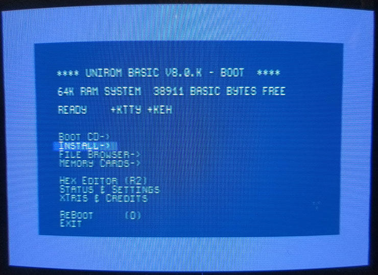
In order for PSX to be able to receive data through the Serial port, one more procedure is first needed – it is necessary that PSX be running on the side of Unirom – it will receive data and execute commands.
Downloading unirom boot disk;
Burn the uniroom boot disk to a CD-R (at the lowest possible speed, for reliability. CD-RW will not work!). For example, through imgburn;
Insert disc into PSX. After loading, a menu will appear. Insert into any memory card slot. Choose install to memory card. Make a record. Of course, you can not write to the memory card and boot from the boot disk each time, but this is inconvenient.
Now, without a disc, insert this memory card into the SECOND slot and when you turn on the PSX, select “memory card” in the main menu of the console. Unirom basic will load.
PSX is ready to receive data.
Further, it is stuck into the Serial port PSX (more precisely soldered, because you will hardly find such a connector) FT232RL FTDI USB to TTL adapter, which must be switched by a 3.3 volt jumper. On the other hand, USB is plugged into it. A minimum of problems – everything worked for me the second time, tk. the first time I confused RX with TX. Win10 immediately recognized the adapter and installed the driver without even asking anything. Adapters are sold freely, at least on Ozone. The main thing is to see that there is a switch of 3.3 volts.

Now download nops.exe (package NOTPSXSerial) and run it with view parameters:
nops /exe /fast helloworld.exe com7
The code is loaded into the PSX and runs immediately. You can download the binary and run it from a given address:
nops /fast /bin 0x80010000 test.bin com7
nops /fast /jmp 0x80010000 com7
I note that nops / ping does not work for me, but there are no problems with data transfer – keep in mind.
The /fast switch increases the speed to 518400 (instead of 115200).
There are many other parameters, in particular for debugging. But I didn’t need it.
I will add that for all these operations PSX must be chipped. Those. modified so that it can read not only branded discs, but also those recorded by anyone.
In principle, we probably don’t sell unchip ones, but still you need to ask when buying.
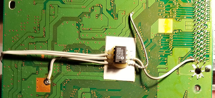
Chiping visually looks like a small chip with wires stuck to the back of the board. There are complex ways to do without chipping, but there will be more problems than savings.
Intro
As usual, in order to get a feel for the platform in practice, I wrote small (812 bytes) simple intro – something like blue plasma under the sound of the waves.
I already wrote about the implementation of noise (in this case, it is still periodically restarted by the counter), and as for the plasma, the ability to draw quadrangles with a gradient Gouraud fill in hardware was used.
The corners of the quadrilateral correspond to the corners of the screen, and in each of the corners the color changes cyclically from black to blue and back. Moreover, the phase and speed of color change in different angles are different, so the changes seem more or less random.
I believe that if you tinker a lot, you can reduce the amount of code by one and a half to two times, but still – for such a primitive effect, which is also performed by the GPU, the MIPS architecture requires an unreasonably many bytes.
Epilogue
I once wrote that creating programs in assembler for old hardware, as it were, establishes a connection with the people who made it. So, specifically with the PSX, this is no longer felt. Programming for him is more like STM32 programmingthan say TI 99/4a or Commodore 64.
In particular, everywhere you need to initialize a lot of registers, without which nothing will work at all. There is no reasonable “default” setting for anything in the system. It is very felt that the developers of the hardware did not worry at all about those who would program it directly – it is expected that people will use the proprietary SDK and write in C.
Actually, the vast majority of demos, intros and games created after the PSX “left the stage” are written in C. True, this was done in those years when Win95/98/XP was relevant and, accordingly, it was possible use old SDKs.
Finally, the Cracktro collection for PSX:


