A monitor that counts its operating time
As the dear reader may guess, we will again talk about the LightCom monitor and the microcontroller built into it from the Milander company.
Summary of previous episodes:
Hidden text
A blogger discovered a Taiwanese chip from Realtek in a Russian monitor with 140 localization points (link)
Lightcom and Milander consider the incident to be black PR; in response, the blogger posted a photo and a diagram for removing an unnecessary chip (link)
The Association of Developers and Manufacturers of Electronics of the Russian Federation issued an open letter in support of LightCom and Milandr (link)
The Lightcom company filed a lawsuit against blogger Maxim Gorshenin (link)
On March 20, a video was released on the Notebook1-Service Youtube channel, where Alexey Yuryevich worked closely on the LightCom V-Lite-S monitor that had fallen into his tenacious paws.
The video contains a lot of technical details that were so lacking in the original video from Maxim Gorshenin, but the information is presented in a fairly simple and understandable language.

Screenshots of part of the text of the statement of claim from LIGHTCOM LLC to:
Maxim Vladimirovich Gorshenin
LLC “ZEN.PLATFORM”
LLC “RUFORM”
YouTube Companies (GOOGL LLC)
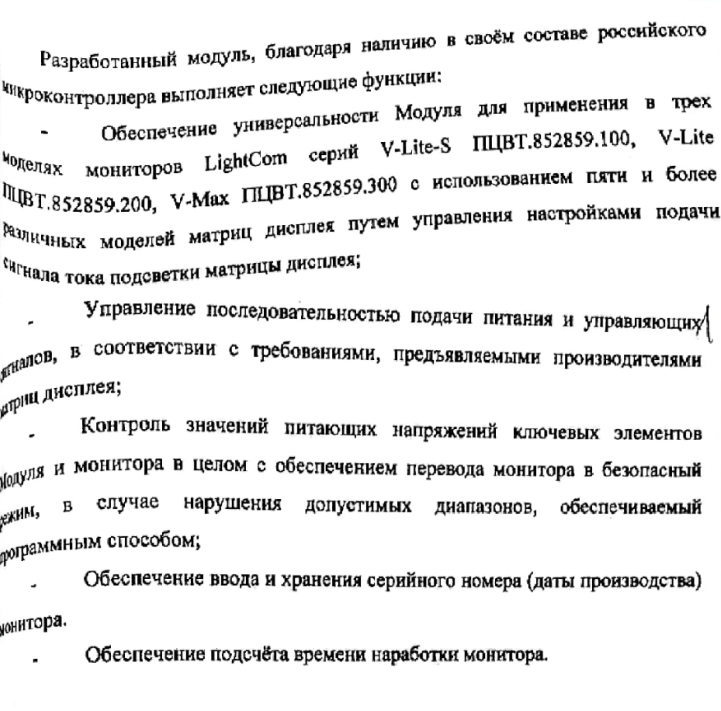
The statement of claim describes the functions that the microcontroller performs:
Ensuring the versatility of the Module for use in three models of LightCom monitors of the V-Lite-S, V-Lite, V-Max series using five or more different models of display matrices by controlling the settings for the display matrix backlight current signal;
Instead of installing one or two current-setting resistors with a certain value for a specific display matrix, this versatility is achieved by using a microcontroller and a resistive matrix.
Controls the sequence of power supply and control signals, in accordance with the requirements of display matrix manufacturers;
Monitoring the supply voltage values of the key elements of the Module and the monitor as a whole, ensuring that the monitor is switched to a safe mode in case of violation of the permissible ranges, provided by software;
There is such a theoretical possibility, but as shown in the video, the monitor turns on and works despite the fact that the resistors that divide all measured voltages have been removed. And now it is not clear whether these two above-mentioned functions are fiction, or whether someone took a creative approach to checking the presence of supply voltages in the firmware.
Ensuring the entry and storage of the serial number (production date) of the monitor.
This is usually done using a sticker on the board and monitor.
Providing calculation of monitor operating time.
?!
Unfortunately, curiosity was only partially satisfied, because… The controller firmware could not be dumped. The board also has a soldered Serial Wire Debug (SWD) port and UART.

It would be interesting to see if any CLI interface is available via UART, for example for “managing the display matrix backlight current signal settings”, viewing/changing the “serial number (production date) of the monitor”, as well as viewing the “current operating time of the monitor”.
Perhaps the SWD port will allow you to dump the firmware; support for MDR32Fx internal flash memory was added to the OpenOCD utility back in August 2013 (link), and here is an example of how to work with it via SWD (link).