WS2812B
I bought two options for testing LEDs with a built-in driver at once, in the version of a separate driver and in the version of the LED. Realizing that a radio amateur who did not blink beautifully with diodes is not a radio amateur. I also unsoldered my primitive flasher, essentially a debug board.
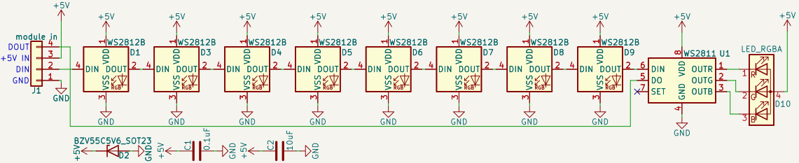
scarf
Round number of LEDs (8 pieces) + 9th LED with driver for testing. In addition to the LEDs themselves, judging by the datasheet, nothing is needed, even shunt capacitors of 0.1 uF. Although for a variant with a separate driver, a capacitor is advised. Separately, they advise, but do not oblige to spare the microcontroller port, and at the same time the output port of the LED with a 30 Ohm current-limiting resistor. I do not forgive myself for mistakes, therefore I neglected them. That’s what modern highly integrated solutions mean, the board is freely displayed in one layer. As a result, you can safely connect to the controller. There remains one problem, the LEDs are powered by 5V, and are designed for a five-volt I / O port, and in STM32 3.3.

I/O port (5V and 3.3V compatible)
Judging by the datasheet for the old microcircuits of the 70s, the unit starts with 2.4V, and the voltage drop on the Pull-Up transistor of the microcontroller is 0.2V and not more than 0.3V. It turns out that + 3V at +2.4 maximum allowable is already on the verge, but in most cases it can work. Rolled here too.
To be honest, then in the case of the STM32, not all ports are suitable, but only those that allow 5V. The difference between ordinary and five-volt ones is one, on ordinary ones there is a protective diode that equalizes the voltage with the supply voltage, which will not allow 5V to be applied. Five volts are labeled FV in the datasheet. As a result, to work with five-volt logic, you need to configure such a port in open drain mode by pulling it up to + 5V with an external resistor. But here another oddity was noticed, or there are no five-volt ports, or the WS2812 port is very voracious. It turned out to form 0-5V only with a 500 ohm resistor, with kilo-ohm resistors the unit dropped to 3.4V. But again, all these tricks are optional, because it rolls like that.
LED protocol
Access code for LEDs in file ws2812.c. The datasheet says something about NRZ, but I smell that their protocol is similar to 1-wire in DS18B20. The only difference is that the timings there are nanosecond, while on ds they are microsecond. It is more difficult to organize such a protocol, atmega drivers write code in assembler to support the required timings with a strictly measured number of NOPs. In the case of STM, you can get by with a regular timer, the main thing is to remove unnecessary junk from the data transfer function to the LED, like calling other functions, then it will turn out to fit into strict timings. It didn’t work out for me right away, I didn’t immediately understand that the timer for the next bit needs to be reset at the end of the cycle and not at the beginning, because. otherwise, each bit takes not the same time and it knocks down the sending. In general, there were two more extreme options, this is either the use of PWM with DMA, or UART. In uart, each byte would symbolize a bit (such a trick worked with ds), and in varying the PWM duty cycle by dma, it would also be possible to supply 0 and 1. But again, since I’ve rolled the manual version, then let it work, and me buffers with an int for each bit are unimpressive.
Other features
Apparently due to the convenience of wiring, the LEDs are not RGB but GRU, or rather GRB. While the driver is normal, RGB. I had to add a separate function to flip back and forth. Otherwise, it is very convenient to declare a union which is when you need three variables of 8 bits each with red, blue and green colors, and for the sending function one 32-bit number. As a result, everything happens inside the library, and you need to cram an array of structures with LED colors into a function wsUpdateCascade(*led_array, size)not forgetting to indicate which of them is the 11th and which is the 12th in the field type. This is where the low-level torment ends and the fun begins.
Random
What are the effects without randomness. Fortunately, you don’t have to go far for an integer random number. I downloaded the AVR-libc sources and copied the function from there rand. There it is integer and 32 bit, what is needed for STM32, but not for mega. I love opensource for such opportunities.
effects
Never thought of more than three. The effects lie in file.
Rainbow, in which all the LEDs are lined up in all the colors of the rainbow and smoothly flow from one color to the next.
From the series Knight of the Roads with a running light, and also emulation of a sticky light, like on incandescent bulbs. Added a pre-written rainbow function to it.
Fire. Dumber than everyone else, just shove a random number 0–255 into the red channel. And so that the light shimmers from red to yellow, we generate randomly for the green channel, but do not let it be brighter than a quarter of red. And we also catch the moments when red is more than 250, then we turn on all the colors to emulate sparks.
On the one hand, this is an ordinary routine debugging board, on the other hand, you can get stuck near this strip for half a day, and the Internet is full of independent megaprojects that offer nothing but the same lights. Effects are scalable, you can sew them into your controllers with LED strip by changing the macro line size at your discretion.
Conclusion
Wonderful rubbish these RGB LEDs. A separate driver and LEDs in the same circuit got along well, no external elements and assembler code inserts were needed. More of such a cheap Chinese integral, easy to use and sticky, and tik tok will not be needed, it will be yours.