We extract the GameBoy firmware from the photo of the chip
Hi all!
You are offered a small quick tutorial on how to restore the GameBoy firmware. Let’s start with photos depicting the firmware with metal joints (mask ROM) from the Nintendo GameBoy – and the output will be a ROM file that can be disassembled or emulated.
The GameBoy gadget is well suited for this, since it uses the so-called “permanent memory programmable by jumpers” (Via ROM). This means that individual bits are encoded by metal bridges between layers, and these bits can be read from the surface of the chip. In addition, the firmware itself is small enough that I was able to include it in the Github repository, thereby saving you weeks of time that you could spend on fixing small bit errors.
Hello from Knoxville,
— Travis Goodspeed
Photo
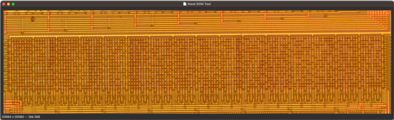
Let’s start with a snapshot of dmg01cpurom.bmp, which I took in my home lab, after decapsulating the chip in nitric acid and cleaning it in acetone in an ultrasonic bath. Such a chip does not require exfoliation in hydrofluoric acid or staining of bits with a Dash Etch solution consisting of nitric acid, hydrofluoric acid and acetic acid.
The photograph was taken under my metallurgical microscope as 22 frames at 50x magnification, which were then stitched together with Hugin. A biological microscope will not work in this case, since the silicon substrate is impervious to visible light. In contrast, under a metallurgical microscope, light reflects off the sample instead of penetrating it.
My original image was too big (and couldn’t be uploaded to Github), so here’s a lower resolution version for you to work with. Lossy compression was avoided, as this technique can lead to confusion in image recognition.
If you take a picture of the DMG-01-CPU chip yourself, then the instructions below will apply to it.
Extracting bits
In this tutorial, we will be extracting bits using MaskRomToolmy CAD program, which allows me to do just such operations very quickly.
First, let’s compile MaskRomTool and install it. If you are on “you” with the unix command line, then you must arrange that the executable file maskromtool stayed with you $PATH. If not, just skip this part, since all the features are available through the GUI.
After running this program, open the file with MaskRomTool dmg01cpurom.bmp.
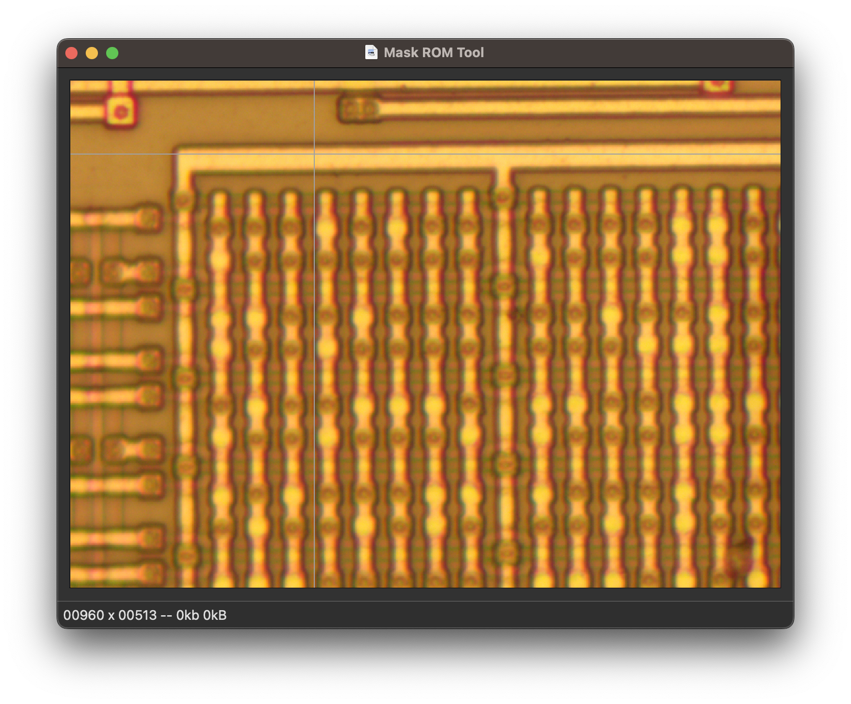
Note that the mouse is followed by a gray cross. At first it is flat, but gradually its shape will begin to change to match the rows and columns that you impose on the firmware. Thus, on one side of the monitor, it is visible which bits will be on the other side of the monitor.
Also note that the bits in the firmware come in pairs of regular rows and groups of eight regular columns. In MaskRomTool, you will arrange rows and columns, but we do not have strict rules that these groups would have to be exactly the same as in the original image. If you find that you can reliably position a huge row that intersects the entire width of the image or, conversely, a column that spans the entire height of the image, do so, do not hesitate.
Navigation
Line spacing
Let’s start with a few short lines, and later try with long ones. First click the mouse to the left of the leftmost bit, and then move the cursor to the right, but NOT click. Instead, press the R key to put a line (Row). A thin black line will stretch between these two points.
You can do this as many times as you like and space out all the lines, but it’s cumbersome, and when working with the longest lines, you’ll have to scroll a lot. It is better not to move the mouse away from the right edge, but just slowly move it down. When the “sight” is equal to the desired line – press Shift + R or space to put another line.
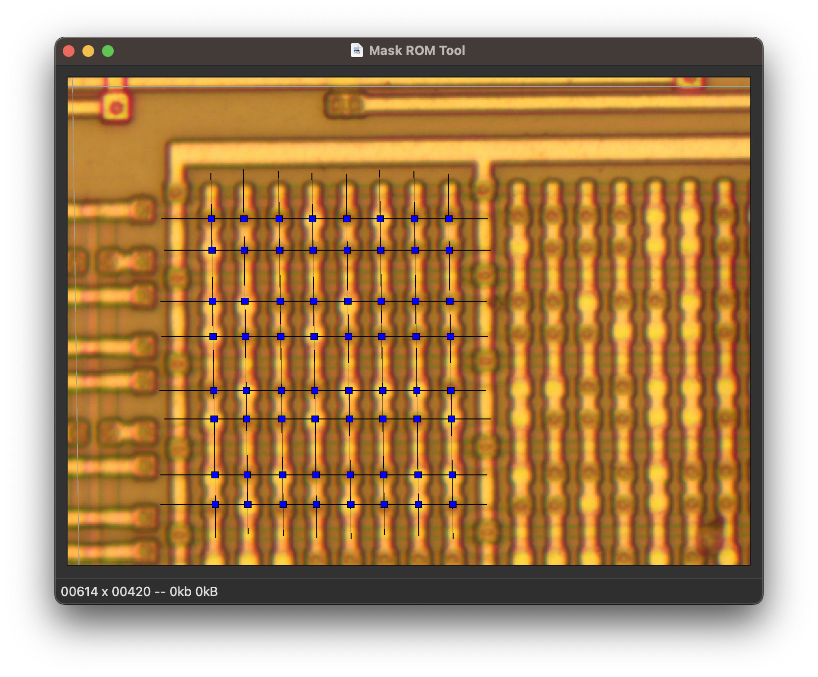
If you repeat this operation with many lines, then very soon they will all be marked up. In the following screenshot, I’ve marked out the short segments of the first eight lines.
Once you get the hang of arranging repeating lines while sticking to the right edge, you can also mark them across the whole picture – this will save you time and effort. If you can’t get straight lines to cross the entire image, then mark out shorter sections or, even better, adjust the panorama from which the photos are taken.

Column arrangement
Despite the fact that you have already marked several columns, the program still “does not know” where the bits are, since you have not yet marked a single bit.
To mark the first column, first click on the top bit of your first column. Next, just like when working with a row, move the mouse cursor under the last digit in the column and press Shift+C to draw a column line (again NOT click.)
Repeat so on, placing the cursor under the next extreme bits and pressing Shift+C. As each column is pulled through the rows, blue squares will appear above each bit. The program already knows where the bits are, and then we need to teach it to distinguish zeros from ones.
Bit recognition
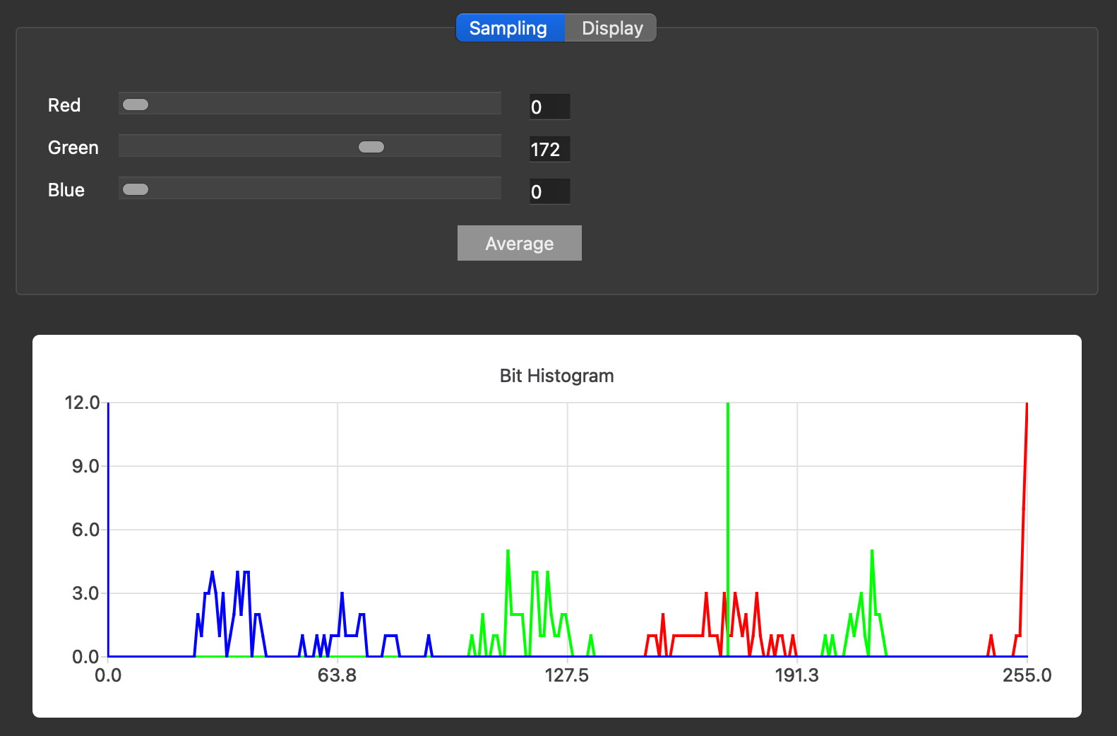
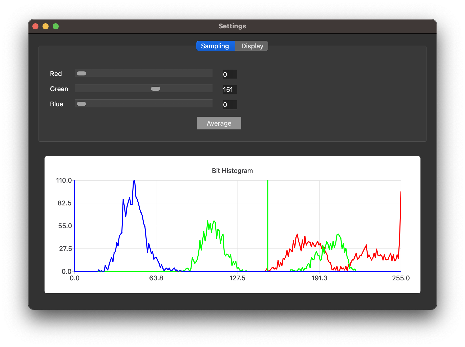
In order to detect bits, the program must have not only their positions, which you provide, but also a threshold value, as well as a color channel to distinguish between bits. Click “Edit” and then “Choose Bit Threshold”. As a result, you will see the following diagram and you can choose the threshold value that suits you.
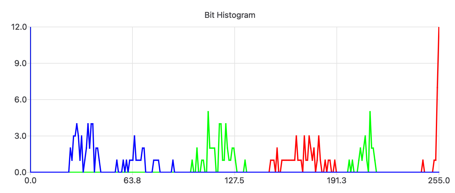
This histogram shows gaps in all color channels for the first 64 bits. The largest gap is in the green channel, so for this channel I would set the threshold to 172. Notice how the bitboxes automatically resize when you adjust the threshold.
Although the blue and red channels for this image look tolerable, we are interested in the green channel, since it is in it biggest space. When we start adding bits to the image, we need to pick up the color differences more – so we are guaranteed to get less bit errors.
With the first sixty-four bits set, click View and ASCII Preview to make them visible. Pretty, right?
11101011
01111111
00110111
01101111
10110001
01101110
01011100
10110101
More beats
Now, having practiced recognizing the first sixty-four bits, let’s recognize all the bits in the picture.
First, let’s erase all our previous work. To do this, you can either remove
dmg01cpurom.bmp.json and open dmg01cpurom.bmp in a newly called Mask ROM, or erase all your lines en masse. To erase the lines in bulk, select them by dragging the edge, and then cut them all at once by pressing Shift+D.
(Strictly speaking, it would also be possible to mark up the image with many very small rows and columns. The only reason I don’t recommend doing this is not because the method won’t work, but because it could take forever.)
After erasing all the lines, put a new one that will stretch from the left edge of the screen to the right. If you decide to overwrite previously done work, rather than deleting it beforehand, then it helps to start with a relatively short line so that the slope of the cross cursor matches the slope of the image. Then you can try to skew each line with R, then delete the unnecessary with D, and the program will still not forget which position was the start.
Having drawn the first line, drag the mouse cursor along the right edge of the photo of the firmware, pressing Shift + R or space each time you complete the next line – to lay another line below. If you notice that when marking a bit, the S key will help – it sets the position of the last line, this line is moved with the mouse to a new location.
After drawing long lines, start drawing columns. To set a starting point, simply click once above each top bit, then hold C and drag down to create a column. If you press Shift + C, then a new column will be laid at the same angle at the other extreme point. Therefore, you can go through the whole picture in this way and quickly draw all the columns.
When all the bits are set, use the Edit / Choose Bit Threshold / (Select Bit Threshold) commands to slightly adjust this threshold. Note that with this many bits, the curve is much smoother, and therefore it may be more appropriate to stop at 151 rather than 172.
Finding and fixing bugs
It’s nice to feel when all those bits are marked up, but usually the work doesn’t end there. Before proceeding with the decryption of the firmware, it’s good to do a few quick sanity checks to make sure we haven’t made any mistakes.
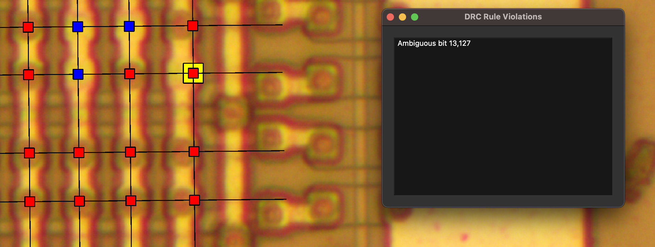
With the V key or the DRC/Evaluate Rules command, you can quickly check how well you designed everything. For example, what if you misplaced the line, and the color of the bit turned out to be suspiciously close to the threshold value? You can get something like this DRC error, and it is solved by correcting the line spacing. For each design rule check (DRC) violation, the position at which the error was made is indicated by a yellow square in the GUI.
Mistakes such as incorrect line placement are, of course, your fault, but you also need to correct those errors that you are not responsible for. Sometimes a speck of dust can get into a photograph, hiding the value of a bit at a certain point. Sometimes, due to a bug with reagents, a bit can not be viewed very well.
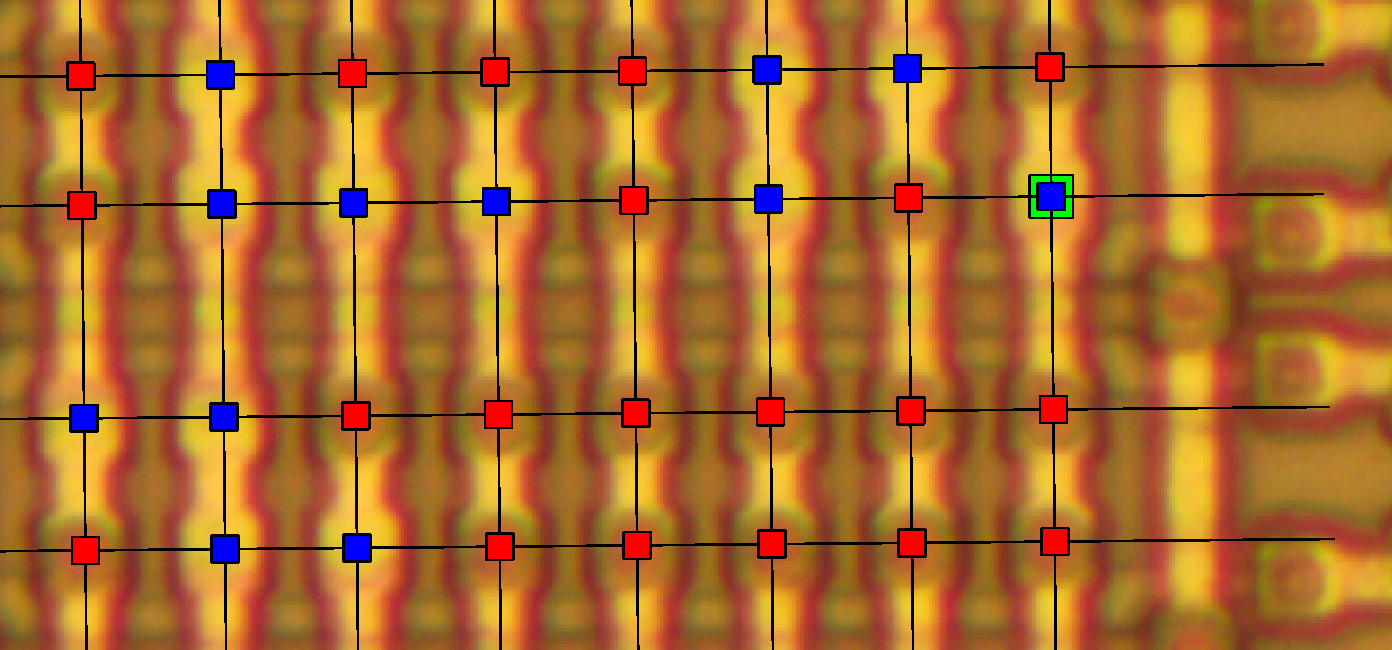
In those situations where you obviously know better than the machine, press Shift+F while the mouse is over the bit to force its value – and put the bit in the green box. If an incorrect value is applied, press Shift+F again and reverse the bit.
When all this is done, the work on beats is finally complete!
11101011111100101100101100110010011000110111110000100001011100101110000000110011110001001001001011000100001011110001101100001000
01111111011100110111111101100011001010110100111100000110101010110011001111110011001010111011000000111000001011101101011011101111
00110111110110110111011111010111011001101001011101111111110110100111000101110010010110000101011101110001111101110111101111011000
01101111111000111110111011110110001011100101011010100010001110000111100000111010011111000111001100101111010000110100111111101001
10110001001100001011100110110111000110011101100111100000111100111111011010110001111111100111011010111010000110100100001100010011
01101110011100110110100100110111011100110101101001001111111100110010111110100011001110011010011101111010000111100111001010110010
01011100011101111111110001110111101100000101101100111000011100010011000011110101001100001011111000110000100110010111011111010010
10110101110101111011101001011111001110101111101000010101111100011101011111000011111010111010101100001110011110011011011111000101
00011111000101000001101110011110101111001111000011111011011100000100011011010000110100111001100100110011110101000101101110110110
11011001000101100111100100011011001110010101010100001101111101110110010110000111010101101101111010101100101100101101111110010111
11111111111110011111101101010101001101111101000010100110101010011011010011111001101101001101010110101010010101011110010110100011
01011110111110100001111011010110001000011101000000111011001011100101001111101110100110110000101000101011100001000001111000100001
11011000100010111011110010010101001011000111000010011000111110001111011011000000100111001101010010001100111101100010100110111001
11111011001010011111101000111101001100101111100110110101011111011011110110000101001011001101000100110111001101011110110110001010
00111111111101100011101111110010001011001111010000011111101111010011011111110111001101110111010101011111111110110101011100111111
10101101111101111000110111110110100001010111100111001101101110100100111111000011011110101010001101011100100011111100111110011111
About CLI
So far, we have been working with our tool through a graphical user interface (GUI). But when you move on to relatively large projects, it may be desirable to automate some things through the CLI (command line interface). By default, when working offline, it is better to set -platform offscreen -eto and avoid opening windows, as well as exiting the program when finished.
Usage: maskromtool [options] image json
Mask ROM Tool

Options:
  -h, --help                 Displays help on commandline options.
  --help-all                 Displays help including Qt specific options.
  -v, --version              Displays version information.
  -e, --exit                 Exit after processing arguments.
  --opengl                   Enable OpenGL.  (Not yet stable.)
  -d, --drc                  Run default Design Rule Checks.
  -D, --DRC                  Run all Design Rule Checks.
  --diff-ascii <file>        Compares against ASCII art, for finding errors.
  -a, --export-ascii <file>  Export ASCII bits for use in ZorRom.
  --export-csv <file>        Export CSV bits for use in Matlab or Excel.
  --export-json <file>       Export JSON bit positions.
  --export-python <file>     Export Python arrays.
  --export-marc4 <file>      Export MARC4 ROM banks, left to right.
  --export-arm6 <file>       Export ARM6L (MYK82) ROM.
  --export-photo <file>      Export a photograph.

Arguments:
  image                      ROM photograph to open.
  json                       JSON lines to open.
Firmware decoding
Now that your project is marked up and all the bits look accurate, you will need to transfer the bit file to other tools so that it can be decoded. Best for this purpose Zorrom is a collection of Python scripts compiled by John McMaster.
Decoding with Zorrom
First we need an ASCII file that contains all the bits of the firmware. In the GUI of the tool MaskRomTool this file can be generated with the File / Export / ASCII commands (File / Export / ASCII), and from the CLI the same operation is done like this: maskromtool -platform offscreen dmg01cpurom.bmp -a DMG_ROM.txt -e.
Further, as described in the Zorrom documentation, you can order Zorrom to present us in decoded form all those bits whose first byte is equal to 0x31. (In GameBoy 0x31 is an operation code that allows you to set the value of the call stack and, it is logical to assume that this is the first instruction in the firmware).
air% ./solver.py --bytes 0x31 DMG_ROM.txt DMG_ROM
Loaded 128x x 16 h => 2048 bits (256 words)
66 match True, score 1.000
  r-180_flipx-1_invert-1_cols-left
69 match True, score 1.000
  r-180_flipx-1_invert-1_cols-downr
Tries: 80
Best score: 1.000, r-180_flipx-1_invert-1_cols-left
Keep matches: 2
  Writing DMG_ROM/r-180_flipx-1_invert-1_cols-left.bin
  Writing DMG_ROM/r-180_flipx-1_invert-1_cols-downr.bin
air%
Given two potential values, you can disassemble each one to find the correct one. And indeed, r-180_flipx-1_invert-1_cols-downr.bin contains the necessary bytes, since it loads 0xFFFE to the stack pointer.
air% r2 -a gb r-180_flipx-1_invert-1_cols-downr.bin
[0x00000000]> pd 1
            0x00000000      31feff         ld sp, 0xfffe
^D
air% r2 -a gb r-180_flipx-1_invert-1_cols-left.bin
[0x00000000]> pd 1
            0x00000000      311147         ld sp, 0x4711
^D
air%