VxLAN fabric part 4. Multipod
Hello, Habr! Still finishing my article series launching the course “Network Architect” from OTUS, using VxLAN EVPN technology. And today we will discuss the implementation of connecting computer rooms or data centers into one VxLAN factory

The previous parts of the cycle can be found at the links:
- Part 1 of the cycle – L2 connectivity between servers
- 2 part of the cycle – Routing between VNIs
- 2.5 part of the cycle – Theoretical digression
- Part 3 of the series – Connecting an external router / firewall
First, let’s decide what connection options exist:
- Multipod
- Multisite
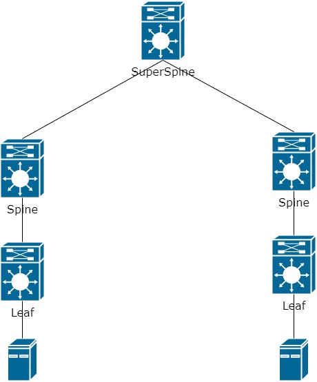
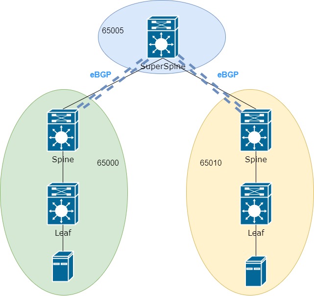
Yes, there are not so many options, but they are enough to solve the problem. Let’s take a closer look at each of the methods. To the previously familiar scheme, we will add a second connection (a second data center or a second computer room), as a result of which we cannot connect the Leaf to the already existing Spine. The distance may be too long or there may be insufficient ports. For simplicity, I’ll leave one Spine and one Leaf switch each. As a result, add another layer to the network underlay – SuperSpine (SS):
Next, we need to build connectivity between the end nodes. And there are quite a few options for the development of events. To begin with, let’s assume that on the one hand we have VNI 10000 and the IP address of the device is in the 10.0.0.0/24 network and on the other hand it is also necessary to use the 10.0.0.0/24 network, providing one L2 domain between different computer rooms or data centers …
As a result of this work, the Leafs need to raise a tunnel through which they will exchange information about MAC and IP addresses:

Good. We decided on the main task. It remains to be seen how to build a tunnel between the Leaf. More precisely, how exactly Leaf learns about each other. As we remember from the previous parts, Leafs are registered on the network using EVPN route-type 3.
There are two ways to transfer EVPN information about the switches themselves and MAC / IP addresses:
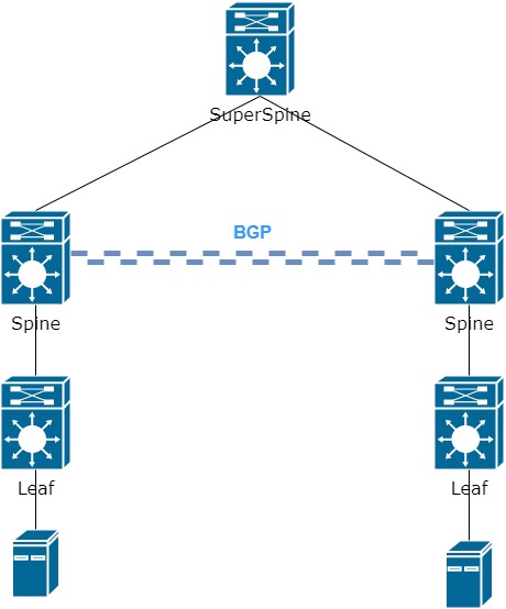
- Raise BGP session between Spines:

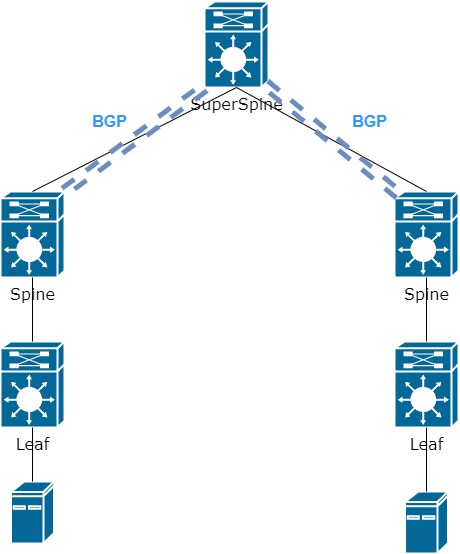
- Raise BGP session between Spine and SS
Again, there are two options for configuring BGP sessions. On both sides, we can use the same AS, then the VNI will look like 65000: 10000, where 65000 is the AS number, 10000 is the VNI number (the numbers are taken from the previous parts).
With one AS, problems in general will not arise. But, as the network grows, managing one AS can be problematic. Since iBGP requires Full-Mesh, or the Route-reflector setting.
Based on all of this, we will be tweaking each part independently. That is, the left Spine is in AS 65000. The right Spine is in AS 65010.
The question remains what to do with SS. Based on the first option, SS can be used purely as an Underlay network. In general, the option is working, but only until 3,4,5 or more Spines connected to it appear on your network. Since between Spines you will have to raise Full-Mesh to transfer routing information.
The second option seems to be more convenient – to bring BGP session to SS with each Spine. Then there is no need for Full-Mesh between separate Spines, which is convenient in terms of configuration and management, but leads to a single point of failure (remember that each device must be duplicated).
Since we previously referred all Spines to different ASs, which SS should we refer to? It’s simple – SS has its own AS:
Now we have an eBGP neighborhood and this attitude leads to the next unpleasant situation, but first, let’s remember exactly how Leaf builds tunnels among themselves. Leaf has information about the Next-hop (NH), behind which is the MAC / IP and the tunnel is being built before this very Next-Hop.
For example, there is the following entry in the BGP table about the MAC address 00c1.6487.dbd1which is available via NH 10.255.0.3:
*> i[2]:[0]:[0]:[48]:[00c1.6487.dbd1]:[0]:[0.0.0.0]/216 *>i 10.255.0.3 100 0 64600 i
This means that the VxLAN tunnel will be built up to the same address. But an eBGP session appeared on the network, in which the Next-Hop address changes when the update leaves the local AS. Therefore, we need additional configuration on Spine and SS, which will prohibit changing the NH address. However, if we are talking about Nexus, then this setting is not as obvious as we would like.
First, you need to create a route-map that prohibits changing the Next_hop address:
route-map NH_UNCHANGED
 set ip next-hop unchanged
Next, it sets the route-map towards eBGP neighbors:
router bgp 65000
  template peer SuperSpine
    remote-as 65005
    update-source loopback0
    address-family l2vpn evpn
      send-community
      send-community extended
      route-map NH_UNCHANGED out
  neighbor 10.255.1.101
    inherit peer SPINE
As you may have noticed, the route-map is set in the address family l2vpn evpn and you thought rightly – SS must also understand the evpn address family in order to transmit information of various types of EVPN. In fact, enabling SS is not much different from connecting a regular Spine in terms of setting up a BGP session.
Well, on this we can assume that the task is completed, but as soon as we begin to check that all information about MAC and IP addresses reaches Leaf, we understand that everything is not so good and update never reached Leaf, but stuck on SS.

That is, all the information reached SS, but he does not send it further. The thing is that the usual BGP logic works here and all these routes do not pass the Next-Hop check, since SS knows nothing about how to get to Leaf (after all, we launched only BGP in the l2vpn evpn address family). To fix this situation, we run OSPF between Spine and SS. That is, now the entire network is a single IGP domain. SS learns about all NH and calmly passes routing information on.
Now we happily check that all EVPN route-types 2 and 3 and 5 have reached the Leaf, but most likely we will be disappointed again. In the routing table, we don’t know anything about remote devices from the remote Leaf.
Remembering the first part, the VNI setup looked like this:
evpn
  vni 10000 l2
    route-target import auto
    route-target export auto
Route-target is generated automatically based on AS: VNI number. As a result, RT export for the left side is 65000: 10000. For the right – 65010: 10000.
Since import rules work in the same automatic mode, the switch will not add a route with unknown RT to the routing table.
Here you can proceed as follows. Set RT manually instead of automatic mode:
evpn
  vni 10000 l2
    route-target import 999:10000
    route-target export 999:10000
The same goes for l3 VNI (if needed):
vrf context PROD
  address-family ipv4 unicast
    route-target both 999:99999
As a result, the same RT is used on all Leaf switches, along which the route will be added to the routing table and there will be connectivity between end devices