True RND or what to do with the trained model (teapot experience)
Once upon a time on the Internet I read an article about generating a truly random password. The bottom line was that in order to implement randomness, you need to naturally throw dice. Great idea for a small pet project and to get into the basics of ML.
Let’s try to teach the computer to throw real dice, find them on the image from the webcam and understand what fell on them. And so, from improvised materials we make a stand for throwing bones.

I chose twenty-sidedth bones, although this is not essential.
We connect aduino to the driver and the brake solenoid, Next, arduino listens to commands on rs232, turns off the brake and turns on the motor, or vice versa.
sketch
int drive = 11;
int brake = 10;
void setup()
{
Serial.begin(9600);
Serial.setTimeout(5);
}
void loop()
{
if (Serial.available())
{
int val = Serial.parseInt();
if (val == 123) {
digitalWrite(brake, LOW);
digitalWrite(drive, HIGH);
}
if (val == 234) {
digitalWrite(brake, HIGH);
digitalWrite(drive, LOW);
}
}
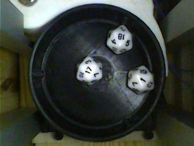
}First you need to create a dataset. In any language, we make a program that sends commands to roll the dice to RS232, and then saves the frame from the camera. We get pictures like this:
We do markup. To do this, I threw a program that builds a circle from the coordinates of three points, finds the coordinates of its center. Next, click the mouse in the corners of the bones, and save along with the file name in csv. But after marking 700 pictures, I realized that something needs to be changed.
Let’s go from the other side. On the marked-up pictures, we cut out round areas with bones, save them in png, since we don’t need everything that is outside the circle, we immediately put them into folders in accordance with the numbers that have fallen out. We take some pictures without bones. Next, we simply place 3 random bones in random places on the background image. Here you need to take into account that the bones cannot intersect and must be located inside the glass.

Thus, we create 100,000 pictures, keeping the markup.
Don’t forget about the main ML formula: shit in = shit out
Therefore, we will evaluate the resulting dataset using a simple model based on Xception.
baseline
base_model = Xception(weights="imagenet", include_top=False, input_shape = [480, 640, 3])
base_model.trainable = True
#Устанавливаем новую «голову» (head):
x = base_model.output
x = GlobalAveragePooling2D()(x)  #Pooling слой
x = BatchNormalization()(x) #добавим Batch нормализацию
x = Dense(256, activation='relu')(x) # полносвязный слой с активацией relu
x = Dropout(0.25)(x) # полносвязный слой с вероятность отключения нейронов в слое
output = Dense(6,  name=out_key)(x)

model = Model(inputs=base_model.input, outputs=output)
At the output of the model there are 6 numbers corresponding to the coordinates of the centers of the bones. I checked it on real pictures, 80 percent was recognized something like this:

the rest like this:

Conclusion: a synthetic dataset is quite suitable for training. Next, we will train Yolo3. Let’s take as a basis this implementation. There are many implementations, but few that work out of the box.

Result: we are great, we trained a cool model that coolly finds bones and … that’s it. What to do with her next? How to “install” it to your grandmother?
You need to be friends with her, for example, with C # and make a normal application with a user-friendly interface. There are several options to make friends with C# model. Consider ONNX. So, let’s convert the model to the onnx format. Next, look in Google or YouTube tutorial for example this. We try to repeat and … the code does not work. But the performance of the code is captured on video! We look very carefully and install exactly those versions of the libraries. It works now.
But the model does not see anything. Let’s assume that C# feeds the image to the grid differently than Python. Let’s check.
To do this, we will make a small grid that will take a 3 * 3 image as an input and simply output 27 digits corresponding to the colors of the pixels as an output.
test model
input = Input(shape=[IMG_SIZE, IMG_SIZE, IMG_CHANNELS], name="image")
output = Flatten()(input)
model = tf.keras.models.Model(input, output)
Let’s give it a blue picture in Python and C# as input, compare the results:

We see that, unlike Python, C# first extracts all bytes of the same color, then the second and third.
We indicate in the pixel extractor what is not necessary, and at the same time indicate the correct order of colors.
code
...
.Append(context.Transforms.ExtractPixels(outputColumnName: "image",
                                         orderOfExtraction: ImagePixelExtractingEstimator.ColorsOrder.ABGR,
                                         colorsToExtract: ImagePixelExtractingEstimator.ColorBits.Rgb,
                                         interleavePixelColors: true
                                        ))
Well, now, the model sees everything as it should be. Let’s go back to the library version. If you believe that here written by Microsoft decided to remove Bitmap support, because this entity is only in Windows. Instead, they suggest using MLImage. I love it when authors change interfaces. Let’s try. And when we pass the image loaded from the file to the model: MLImage.CreateFromFile(String) there really are no problems.
But we want a webcam, in real time, and not just watch, but draw in every frame. Google has a lot of examples of how to work with a webcam using Emgu.CV. And what is most captivating is that they work without dancing with a tambourine.
Emgu.CV extracts frames from the webcam into objects of type Mat. In fact, this is just a matrix, in our case, bytes. An MLImage can be created from a linear array of bytes: CreateFromPixels(Int32, Int32, MLPixelFormat, ReadOnlySpan
We draw out our Mat and try to create an MLImage.
code
Mat m = new Mat();
webcam.Retrieve(m);
Bitmap img = m.ToImage<Bgr, byte>().ToBitmap();
byte[] barray = new byte[img.Width*img.Height*3];
m.CopyTo(barray);
MLImage image = MLImage.CreateFromPixels(img.Width, img.Height, MLPixelFormat.Bgra32, barray);
The Bitmap here is only created for output to the pictureBox. We start and the model sees nothing. Again, we look at how the data is transmitted, and the problem is that the MLImage pixel format always contains an alpha layer, and the Mat from the camera comes without it. Adding alpha:
code
Mat m = new Mat();
webcam.Retrieve(m);
Bitmap img = m.ToImage<Bgr, byte>().ToBitmap();
CvInvoke.CvtColor(m, m, ColorConversion.Bgr2Bgra);
byte[] barray = new byte[img.Width*img.Height*4];
m.CopyTo(barray);
MLImage image = MLImage.CreateFromPixels(img.Width, img.Height, MLPixelFormat.Bgra32, barray);
and we get what we were looking for:

PS. Most of the code in the project was taken from the indicated sources with almost no changes, or with minor adjustments, here I have indicated only non-obvious points. If you are interested in details, write.