Third eye for the blind

In this post, we will talk about the Third Eye for the Blind – an innovation that helps blind people navigate with speed and confidence, find nearby obstacles using ultrasonic waves and notify them with sound or vibration. They only need to wear this device like an elastic band. Under the cut – we understand how it works and whether it can give people without sight hope to see the world again.
According to the WHO, 39 million people are considered blind worldwide. In everyday life, such people experience many difficulties. Victims have been using the traditional white cane for many years, which, while effective, has many disadvantages. Another method is a guide dog, but it is expensive. Therefore, the goal of the project is to develop a more efficient device that will help blind people navigate confidently, comfortably and quickly. Let’s see what kind of device is in front of you?
The first wearable electronics for the blind.
It detects obstacles with ultrasound.
Notifies the user with vibration or buzzer.
How it works?
What’s new in the project?
This project is the first wearable technology for the blind, solving all the problems of existing technologies. Now there are many tools and smart devices that make it easier for the blind to move around, but most of these technologies have certain problems with carrying, as well as a major drawback: it takes a long time to learn how to use them.
One of the main features of the new device is that it is affordable for everyone and costs less than $ 25 (~ Rs 1,500). There are no devices on the market that are as simple and inexpensive to wear as clothing. If the device is improved and if it is used on a large scale, it will bring enormous benefits to society.
Step 1. Existing systems

White cane.
Guide-dog.
Smart devices (e.g. Vision).
Problems of existing systems
The white cane can crack or break easily, and the stick can get stuck in cracks.
A guide dog is expensive ($ 42,000 or INR 280,000).
Common disadvantages (including smart devices). They are not easy to carry, but it takes a lot of time to learn how to use it.
Features of the device for the blind… With the “Third Eye”, you can give up the white cane and other similar devices. It will help the blind to navigate, but not to hold a stick in their hands, which annoys them a little. You can wear it like a ribbon and it will work very accurately. “Third eye” does not take a lot of time to learn.
Step 2. Full description of the project
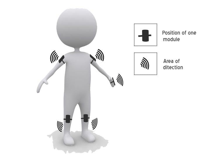
Based on the Arduino board, I developed a special wearable device that the blind can wear like clothes. This device is equipped with five ultrasonic sensors, consisting of five modules, which are connected to different parts of the body. Two sensors for the shoulders, two more for the knees and one for the arm. With these five sensors, the blind will be able to detect objects, presenting their position from five points of view, and will be able to move easily anywhere. When an obstacle is detected, the device notifies the user with vibration and beeps. The vibration intensity and the frequency of the beeps increase with decreasing distance, and the device is fully automatic.
The project can be carried out in the form of a vest, so that the device does not need to be carried as a separate item in the hand. A specially designed board instead of an arduino, as well as high quality sensors, will speed up the device’s response to obstacles – so the “Third Eye” will be able to work in a crowded space.


Step 3. Components of the prototype
Components and tools
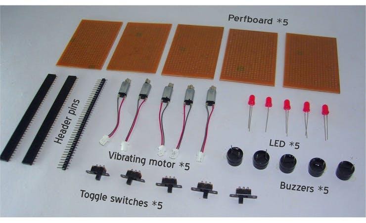
Components
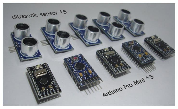
Five SparkFun Arduino Pro Mini 328 – 5V / 16MHz
Five ultrasonic sensors.
Five perforated boards.
Five vibration motors.
Five buzzers.
Five red LEDs.
Five slider switches.
40-pin connector and 8-pin female connector 0.1″…
Four overhead wires.
Old mobile battery 3.3V.
Li-polymer battery 3.7V
Tape and stickers to put on the device.
Tools
Universal soldering iron
Universal hot glue gun
Arduino IDE

Assembly instruction:
Ground the LED, buzzer and vibration motor to Arduino digital ground.
The positive pole of the LED and the middle leg of the switch goes to the Arduino pin-5.
The positive pole of the buzzer is towards the first leg of the switch.
The positive pole of the vibration motor is towards the third leg of the switch.
Ultrasonic sensor.
VCC of ultrasonic sensor to VCC of Arduino.
Ground the ultrasonic sensor to the digital ground of the Arduino.
Connect ultrasonic sensor Trig to Arduino to pin-12 connector.
Connect ultrasonic sensor Echo to Arduino pin-12.
A switch is needed to select the mode: buzzer or vibration.
Step 4. Build modules


Cut the perforated board to 5 x 3 cm and solder the Arduino sockets to the board.
Solder the buzzer.
Connect the vibration motor with a glue gun and solder the wires to it.
Connect LED.
Connect the switches.
Then connect the contacts of the ultrasonic sensors and the battery input.
Solder as shown in the circuit board diagram.
Now connect the ultrasonic sensor to the Arduino board.
Connect all modules with elastic tape.
The same should be done with three more modules, but the sensor in the hand is done a little differently. Watch the next step before you start doing it.
Step 5. Code and manufacture of the arm module
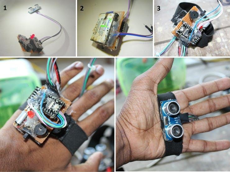
Connect the ultrasonic sensor to the board with four connecting cables.
Then connect a 3.7V mobile battery to this module.
Add an elastic band as shown in the picture.
Finally, upload the code to each Arduino board and power up the other 4 modules using an external battery.
Arduino Code
//VISIT : www.robotechmaker.com
  const int pingTrigPin = 12; //Trigger connected to PIN 7
  const int pingEchoPin = 10; //Echo connected yo PIN 8
  int buz=5; //Buzzer to PIN 4
  void setup() {
  Serial.begin(9600);
  pinMode(buz, OUTPUT);
  }
  void loop()
  {
  long duration, cm;
  pinMode(pingTrigPin, OUTPUT);
  digitalWrite(pingTrigPin, LOW);
  delayMicroseconds(2);
  digitalWrite(pingTrigPin, HIGH);
  delayMicroseconds(5);
  digitalWrite(pingTrigPin, LOW);
  pinMode(pingEchoPin, INPUT);
  duration = pulseIn(pingEchoPin, HIGH);
  cm = microsecondsToCentimeters(duration);
  if(cm<=50 && cm>0)
  {
  int d= map(cm, 1, 100, 20, 2000);
  digitalWrite(buz, HIGH);
  delay(100);
  digitalWrite(buz, LOW);
  delay(d);
  }
  Serial.print(cm);
  Serial.print("cm");
  Serial.println();
  delay(100);
  }
  long microsecondsToCentimeters(long microseconds)
  {
  return microseconds / 29 / 2;
} Schemes
Circuit diagram 1

Arduino Code
//VISIT : www.robotechmaker.com

  const int pingTrigPin = 12; //Trigger connected to PIN 7
  const int pingEchoPin = 10; //Echo connected yo PIN 8
  int buz=5; //Buzzer to PIN 4
  void setup() {
  Serial.begin(9600);
  pinMode(buz, OUTPUT);
  }
  void loop()
  {
  long duration, cm;
  pinMode(pingTrigPin, OUTPUT);
  digitalWrite(pingTrigPin, LOW);
  delayMicroseconds(2);
  digitalWrite(pingTrigPin, HIGH);
  delayMicroseconds(5);
  digitalWrite(pingTrigPin, LOW);
  pinMode(pingEchoPin, INPUT);
  duration = pulseIn(pingEchoPin, HIGH);
  cm = microsecondsToCentimeters(duration);
  if(cm<=50 && cm>0)
  {
  int d= map(cm, 1, 100, 20, 2000);
  digitalWrite(buz, HIGH);
  delay(100);
  digitalWrite(buz, LOW);
  delay(d);
  }
  Serial.print(cm);
  Serial.print("cm");
  Serial.println();
  delay(100);
  }
  long microsecondsToCentimeters(long microseconds)
  {
  return microseconds / 29 / 2;
  }
That’s all, I hope you were interested in this material.

find outhow to upgrade in promising specialties or master them from scratch:
Other professions and courses
PROFESSION
COURSES