Power supply for 5 outputs
For my electronic crafts, I use a homemade 30V 3A regulated linear power supply. It is based on the designer from AliExpress, but I added a few modifications of my own. It has good characteristics in terms of ripple and noise levels, but only one output. When I started the project with operational amplifiers, I needed a bipolar power supply. Then I used two 6F22 Krona batteries connected in series with the middle point. This is a good solution if you do not need high current or voltage (with 9F22 format batteries you can get a maximum of 8.4V, and a nominal value of 7.4V). Well, the batteries have to be charged periodically.
When it came time to connect the analog part with the digital part, we also had to use an adjustable power supply to obtain +5V. Everything was assembled on solderless breadboards and there was no single switch to turn off all the power at once. And the voltage +7.4V and -7.4V from the batteries is sometimes not enough for operational amplifiers. In order not to waste the battery from 18650 batteries, I decided to assemble a simple linear power supply with 5 fixed voltages: +12V, +5V, +3.3V, -5V and -12V. The same voltages are produced by the computer power supply, but there is ripple and noise due to the pulse converter. For the analog part, this can be critical, and filtering interference is more difficult than initially building a linear unit.
As a result, the following requirements were obtained:
linear power supply for 5 fixed voltages: +12V, +5V, +3.3V, -5V and -12V
maximum current up to 1A
switching of all outputs with one button or switch
indication of output current (it is enough for me to distinguish 100mA from 1A)
forced cooling with radiator temperature control
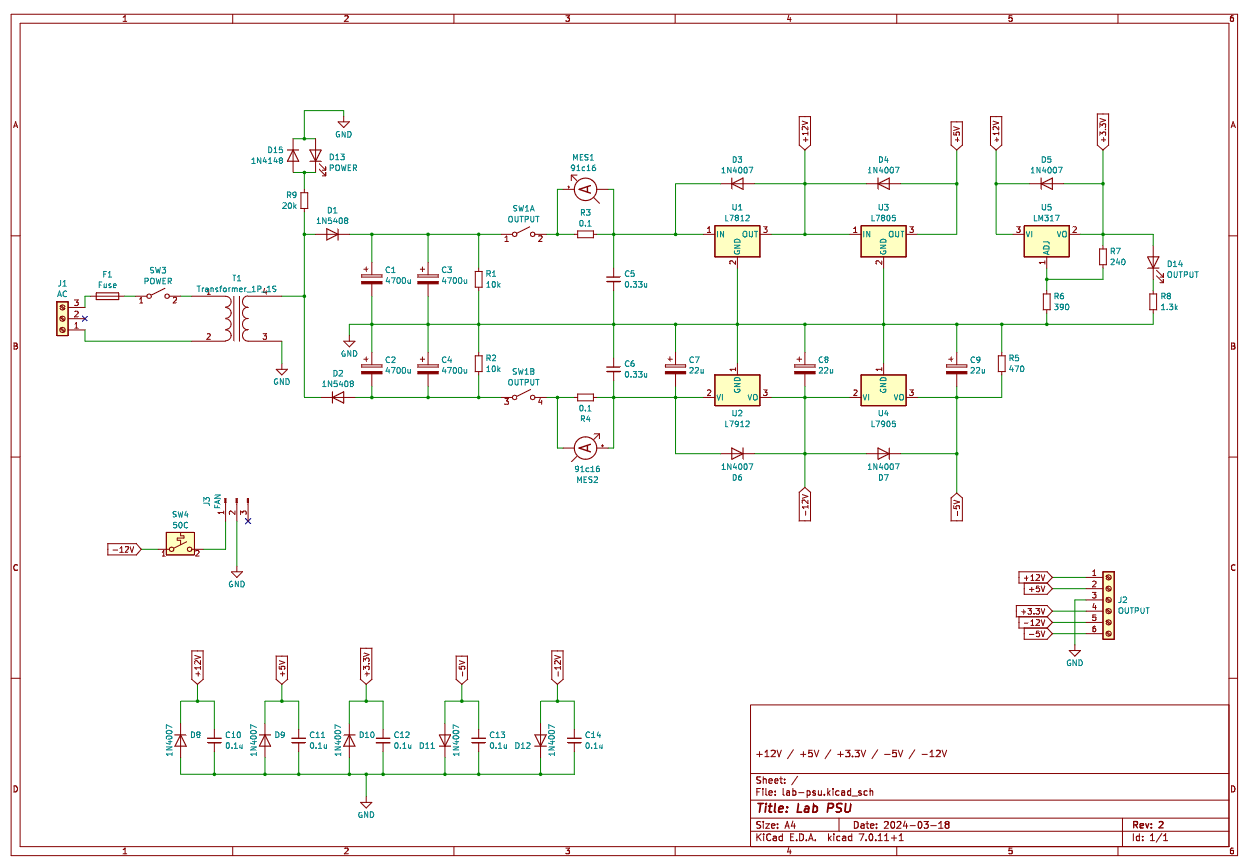
Because The current requirements are small, so I settled on linear stabilizers of the L78xx and L79xx series and chose LM317 for +3.3V. It was possible to build everything on LM317/LM337, but L78xx/L79xx were already available. The connection diagram for the stabilizers is taken from their documentation.

For cooling, I picked up a boxed version of an AMD processor cooler at a flea market, which dissipates 75W of heat without any problems. The fan is switched on via a thermal relay, which is activated when 50°C is exceeded. The stabilizers have built-in overheating protection, so they should not burn out even if the thermostat or fan fails. The heatsink did not fit 7 components in the TO-220 case (especially after the broken screw, which was tightly stuck) and I also had to cut a thread on the top edge. Stabilizers L7812 and L7805 were installed without insulating gaskets (their bracket corresponds to the common output, which are connected together), but LM317, L7912, L7905 and the thermal relay had to be secured through gaskets.
To minimize weight, I used a 40W and 18V toroidal transformer on the secondary winding. It can supply up to 2A current without overheating. The transformer is connected to the network via a toggle switch on the front panel and a 1A fuse. I used the mains power connector without a built-in switch, because… Based on experience with my previous power supply, it is inconvenient to reach to the rear panel.
To obtain bipolar power from one secondary winding, it was necessary to install filter capacitors of larger capacity. Now there are four 4700uF capacitors at 50V (two each for the positive and negative lines) and the output is +25V and -25V. Parallel to the capacitors there are 10 kOhm discharge resistors. The rectifier output is switched by a toggle switch, which disconnects the positive and negative output from the stabilizers. Due to the use of a mechanical switch there is a slight rattle, but this is not critical for me.
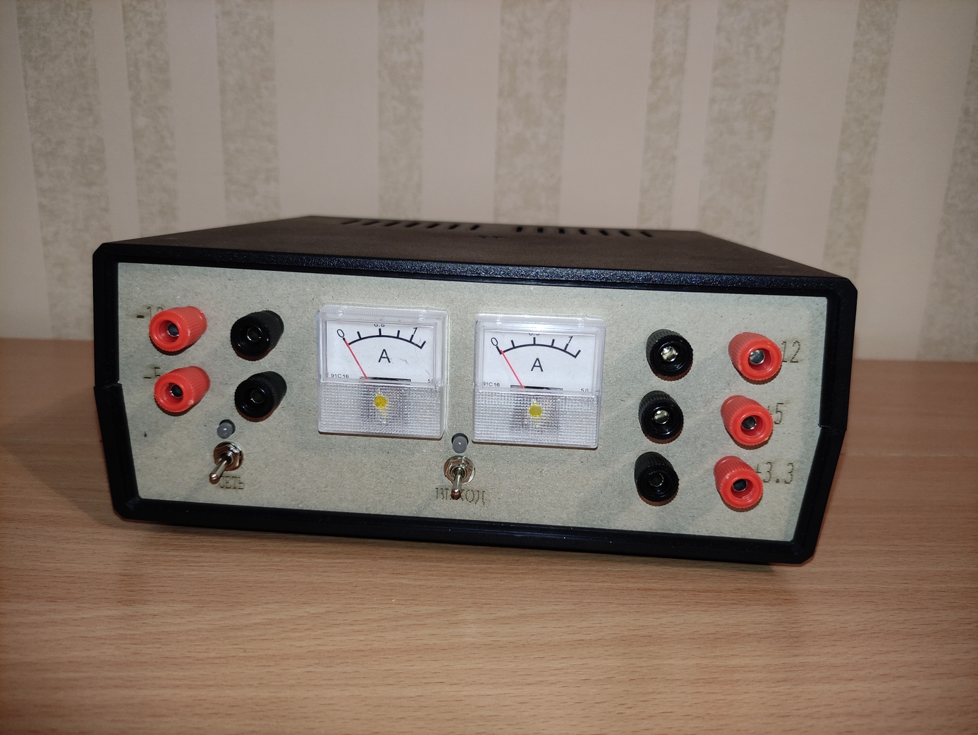
After the output switch there are 0.1 Ohm shunts, which are connected to two ammeters based on 91C16. These measuring heads have low accuracy, they become electrified and begin to lie, but they are cheap and the dimensions are only 40×40 mm. Their accuracy is quite sufficient for working as “display meters”. The maximum deviation voltage for my specimens is around 130mV and therefore the graduation is up to 1.3A. I drew a new scale in Scale Master. In the first version there was only one ammeter, which switched between the positive and negative line shunts, but this scheme had to be abandoned because The toggle switch did not provide reliable contact.
The case was used by Kradex Z17, but at first I tried to cram everything into Kradex Z2A. A special “wow” to the manufacturer whose dimensions of the mountings for the board are asymmetrical and are indicated in fractions of a millimeter, but do not coincide with my copy of the case. I had to bore holes on the board to secure it in the case. The front and back panels of the case are laser cut from 1.5mm cardboard and glued together in two. Thick cardboard was chosen because of the speed of processing – it will take about half an hour to make a prototype at home, and even minutes on a laser cutter. In the future I plan to print these panels out of plastic.


The printed circuit board was made using the LUT method and etched with a solution of hydrogen peroxide and citric acid. This is my first experience with peroxide and at first the etching process did not go well at all – I had to heat it up in a water bath. You just need to take into account that the solution is disposable, but unlike ferric chloride, it does not leave indelible stains on clothes and furniture.

The project files are posted on GitHub.


