NRF5340-DK development board as J-Link programmer
There is an NRF5340-DK debug board that can act as a J-Link programmer.

The NRF5340-DK development board supports programming and step-by-step debugging of external boards with nRF51, nRF52, nRF53 series microcontrollers. In this case, debugging acts as a SEGGER J-Link. To do this, the board has a separate interface MCU (U2)
What do you need from the equipment?
Here is the hardware connection structure
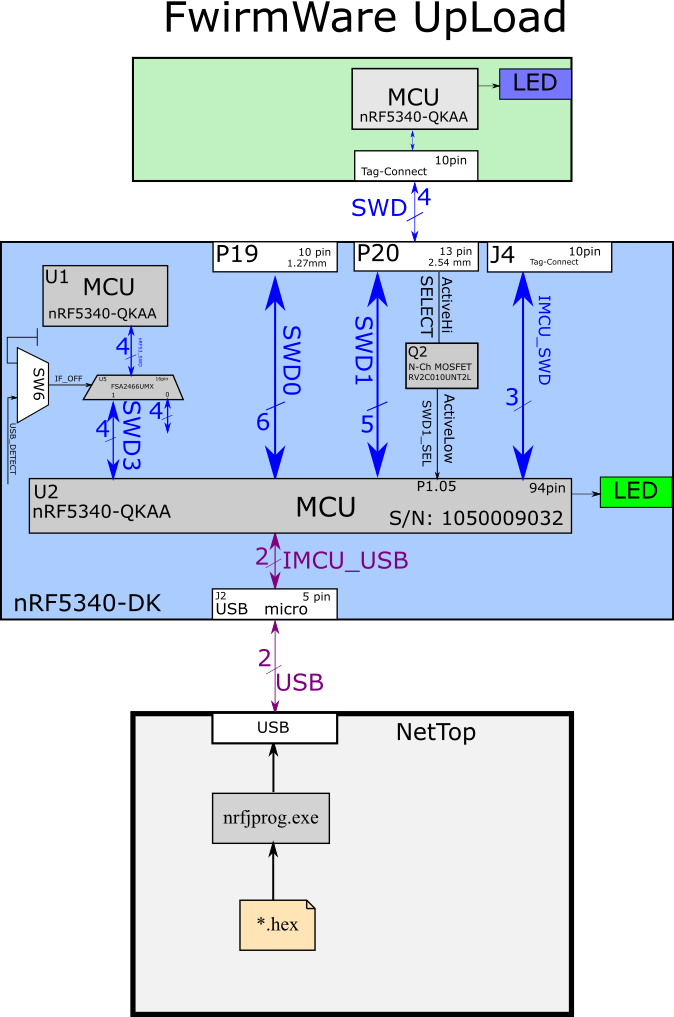
Of the software, only one console utility, nrfjprog.exe, is needed. Usually, after rolling ToolChain (a), it lies at C:\Program Files (x86)\Nordic Semiconductor\nrf-command-line-tools\bin\nrfjprog.exe
When the external board is connected to power, the interface MCU detects the presence of voltage and programs and debugs it instead of the microcontroller on the debug board itself (U1).
If external microcontrollers are connected to all programming connectors at once, then the interface MCU will work according to this priority
A priority | Connector | pins | A comment | Pitch, mm |
1 | P19 | 10 | External target | 1.27 |
2 | P20 | 13 | External target | 2.25 |
3 | — | — | OnBoardTarget | — |
4 | J4 | 10 | Interphase MCU | 1.27 |
The NRF5340-DK has connectors P19, P20 and J4 for programming.

The development board can supply power to the target board through the connector P19. However, for this you need to take a soldering iron and place a drop of solder on SB47.
When programming with a debug board, make sure that the power on the debug board (3V) matches the power on the target board. For reliability, you can power the target board directly from the programmer.
To switch to P20 (SWD1) you need to apply 0V to the SWD1_SEL wire or 3.0 to the P20.3 pin.
Well, we have decided on the connector on the side of the programmer. What’s wrong with the programming connector on the side Target devices? This is how (Fig. 3) the programming connector on the Target side of the device looks like. Do you recognize? This Tag Connect.

There is only one office in the world tag-connect.comwhich makes such freckle connectors and she also declared an embargo on Russia.

In this regard, improvisation begins here. Soldering under a microscope to FootPhint(a) freckles led to this kind of art from the word “bad”.

nevertheless, the U1 programmer found Target and succeeded in flashing it.

Heartbeat LED flashes. Success!
Conclusion
The cost of flashing microcontrollers of the nrf53 series is quite high. Ideally, you need the original Tag-Connect cable, but you can try a more affordable option. On Aliexpess, the gadget is called “2.54mm 2.0mm 1.5mm 1.27mm PCB Clip Clamp Fixture Probe Pogo Pin Download Program Burn DIY”. This is how it looks.

If flashed with original equipment, then it will definitely cost more than 140 EUR (12169 RUR). If you flash with artisanal methods, then it will definitely cost more than 70 EUR (5924 RUB)
Links
TC2050-IDC-NL-050-ALL
https://www.tag-connect.com/product/tc2050-idc-nl-050-all
TC2050-CLIP-3PACK Retaining CLIP board
https://www.tag-connect.com/product/tc2050-clip-3pack-retaining-clip
official spec
https://infocenter.nordicsemi.com/index.jsp?topic=%2Fug_nrf5340_dk%2FUG%2Fdk%2Fhw_debug_out.html
https://docs.jaredwolff.com/nrf9160-programming-and-debugging.html
Analog Tag-Connect(a) https://aliexpress.ru/item/1005004383550982.html?spm=a2g2w.orderdetail.0.0.4e524aa6pJowZ3&sku_id=12000028986468126
Acronym | Decryption |
SB | solder bridge |
SWD | Serial Wire Debug |
USB | Universal Serial Bus |
LED | light emitting diode |
VDD | voltage drain |
DK | dev-kit |
MCU | Micro Controller Unit |
SW | software |

![[HTTP API & REST] Advantages and disadvantages of the HTTP API](https://prog.world/wp-content/uploads/2023/06/733d164a985c9750b53efece1cf82406-768x403.png)