Let's talk about the dacha. From idea to project
“Everything is much more complicated than it seems at first glance”
Murphy's Law.
Disclaimer: The author is absolutely sure that all the problems posed could have been solved in a different way. Better, cheaper, smarter, more creative… But it turned out the way it turned out. Actually, the author adheres to the point of view that the development of dachas is a creative and subjective process: “I am an artist, that’s how I see it.” At the same time, the author is also capable of objective perception of information, and therefore is open to the exchange of opinions and experiences, especially since the creative process continues.
Start here.
So, our “lazy automation” has a “brain”. Now you need to select “arms and legs,” that is, actuators. As I wrote above, at first I thought about solenoid valves. Their simplicity is very tempting – apply voltage and the valve works, remove it and return to its original state. Only two wires are needed. And at first glance, there are a sea of such valves on Ali. The cost of half-inch ones is almost 300 rubles. The execution, however, is not protected, but you can come up with something. However, after reading the reviews, I had to reject this option. The main problem is that they get very hot. They write that in 10 minutes of operation it can heat up to 60-70 degrees. Apparently the Chinese brothers saved on winding. It’s okay for short-term activations, but I need the valve to work for hours. If the valve burns out and we are away, then there will be no one to replace it, and the dacha will be left without watering.
Therefore, I had to switch to another option – a ball valve with an electric motor. In automated process control systems this is called MOV – motor operated valve. For it to work, you already need three wires – one for the opening command, the second for the closing command, and common. There are also many of these on Ali. There is also a two-wire version, where the reverse motion is provided by a capacitor. But how reliable is such a capacitor? In general, I decided not to tempt fate, and took three-wire valves, in a protected version. They operate on 12 volts. The cost of each is around 1200 rubles. I bought three – since the controller has five “open collector” outputs, I decided to leave two in reserve, in anticipation of future ideas and expansions. But still, although such a valve is reliable, I would like to control whether water flows through it or not? Aliexpress came to the rescue again. Half-inch flow sensors were also found there. They are inexpensive, 130 rubles, and the reviews seem to be quite good. Thus, a general scheme began to emerge – we control a pump and three valves, and we control the flow through each valve with a sensor. In the initial position, all valves are open; if necessary, close one or two.
From idea to implementation is a long distance. The scheme so far existed only in general terms, and only in my head. It was clear that the project was growing, and “on the knee”, without at least some minimal documentation, a banal drawing, it would not be possible to implement it. Of course, there were sketches on paper. Clumsy. Very. And I bothered to find a program for drawing diagrams, simple enough to not bother too much, but at the same time quite functional, so that it contained the entire set of primitives and elements.
I began to look towards free software, at first even one that works online, directly from the site. I tried a couple, but quickly became disappointed – either the functionality was weak or the interface was inconvenient for me and took time to master. Therefore, I switched to more traditional software, working from a computer.
Here I must say that I use Linux on my home machines, but I have not yet been involved in drawing in this environment. After some searching, I found a seemingly good package – QElectroTech. Free cross-platform program, there are many positive reviews online. I set it up and started drawing. And again I encountered the same thing – a poor set of primitives, unusual working methods. Of course, you can create your own primitives, or search the network for ready-made libraries and master the techniques, but I didn’t want to waste time on this for the sake of one project.

And then I remembered Visio. I once worked there quite a lot. I also drew electrical circuits. There is still a disk with different versions of this program on the shelf. True, twenty years ago. But for my task, the functionality of those versions is quite sufficient. But there is no Visio for Linux. However, this problem was easily solved – with the help of Wine. He pulled the ancient Visio Technical perfectly. The set of primitives there is from American standards, but for me this does not pose a problem.
And when you have a familiar tool in your hands, and “your hands remember,” then you work very easily and quickly.

“Note in the margins” while drawing – maybe, of course, this is purely my subjective perception, a memory of those times when the grass was greener and the girls were prettier, but the interface of the old Visio seems to me more functional and convenient than the modern QElectroTech – compare at least the area occupied by interface elements, menu bar, tool strip, side sections for selecting primitives, and a panel with tabs. Even on a modern large display there is not much space left for the actual drawing. Visio uses screen space much more economically. Perhaps because twenty years ago the norm was a monitor with a diagonal of 15-19 inches, and not 24, as it is now.
Initially, I wanted to make do with the simplest possible scheme, with a minimum of elements. It would be nice, I thought, if I could control field devices directly from the relay outputs of the controller, and not bother with intermediate relays. But in reality, I still had to “get confused” – the CCU825 has only two “real” relay outputs, but their load capacity is small, and the remaining five are an “open collector”, which will not even pull every relay coil. Accordingly, we had to select the “correct” relays.
At first I thought that it would not be difficult to do this – I was used to the fact that at one time we had “like dirt” at work with these relyushki. Now, faced with selection in a different reality, it turned out that everything is not so simple. That is, on the same Aliexpress you can find any relays you want, and for a very low price, but how reliable are they? Considering that the system had to work in conditions where it was not always possible to quickly find and fix a fault, reliability became of key importance. I had to look for a relay among more or less well-known manufacturers with certificates and clear technical specifications of the products. And it turned out that this product cannot be called cheap. If the “Chinese relyushka with Ali” is 12V. costs 100-150 rubles, then a relay from IEK is already 350. Despite the fact that this brand is not top-end. And relays from brands with a name, such as Schneider or ABB, cost 900 rubles.
That's why I settled on IEK, although according to reviews they are mediocre. I took two more powerful relays, with a load on the contact group of up to 10A – as a replacement for contactors, through which the pump and heating convectors will be turned on. They will be switched through the most powerful relay outputs of the controller.
A small “surprise” was also expected with the terminal block, through which the automation system and cables leading to field devices should be interfaced. Plastic terminals for a screwdriver that fit on a standard DIN rail turned out to be not so easy to find, and the price of one terminal was 30 rubles. That is, a block for 20 elements is already 600. The 220/12V power supply cost 900 rubles, and the box in which all my automation was supposed to fit cost 1300 rubles. In short, the “budgetary” system became, in fact, not so budgetary.
I implemented the circuit in such a way that in standby mode only the controller is powered from the standard 15V power supply. When a command comes to activate any output, the intermediate relay is turned on, and through it an external 12V source. The entire circuit, with the exception of the controller, switches to this source.
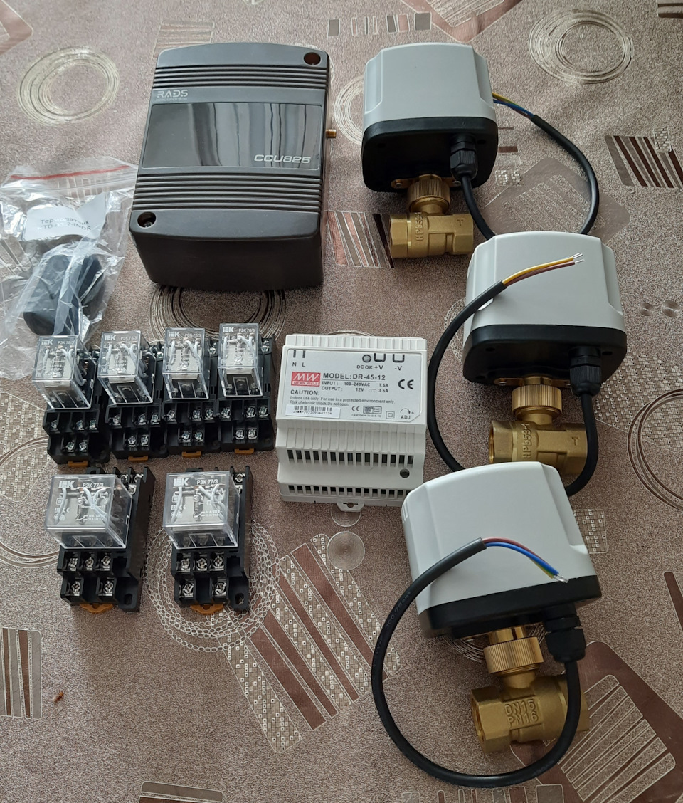
By the end of March, everything was purchased and delivered, and at the beginning of April I assembled the automation. And here is a significant moment – the ball valve opens and closes according to the controller’s commands! Now you can clearly demonstrate to your child what dad does at work.
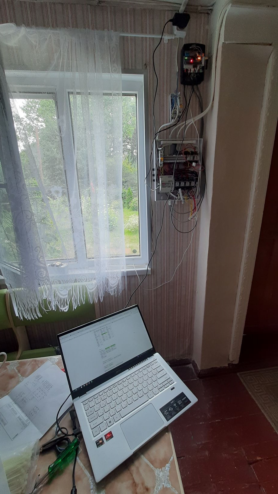
Another note about the CCU825 is that it can connect to a computer via a USB cable. Moreover, all configuration is available via the web interface; no additional application software is required. The only thing you need is to run the ccuproxy console program on your computer. It is cross-platform – the developers did not forget about Linux. And if mobile Internet is available in the place where the controller is installed, then the device can be brought online via an SMS command, and then used for configuration and management using the same web interface, but through the ccu.su portal, where you need to register the controller. In addition, bots in Telegram and VK are also available for management. Very comfortably!
I secured the valves to brackets made of aluminum corners, which I planned to stick into the ground. A hose from the water supply is connected to the valve from below, and a branch for irrigation is connected from above. In this case, the valve will not lie in the dirt on the ground. But in reality, this option did not work well – the outlet hose was bent, creating additional resistance to the flow of water. Therefore, we still had to simply lay the entire structure on the ground. And to protect it from dirt, wrap it in a plastic bag.
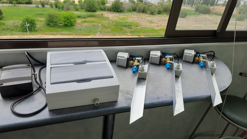
In May, everything was completely ready for installation on site. But it was necessary to prepare the object itself. Namely, lay cables from the house where the controller will be located, along the site, to the valve installation sites. For this purpose, I purchased 70 meters of five-core cable and a protective corrugation so as not to throw the cable into the ground unprotected. I decided to do the cabling along the already completed water route – on top of 32 mm HDPE pipes, routed from the well along the site.
Along the way, the following thought came to mind – what if from each of the three valves we power not one sprinkler, but two? Because it is difficult to cover almost 9 acres of land with three sprinklers. The idea seemed sound, so I purchased three splitters. Thus, there were six watering points, which should have been enough to irrigate most of the property.
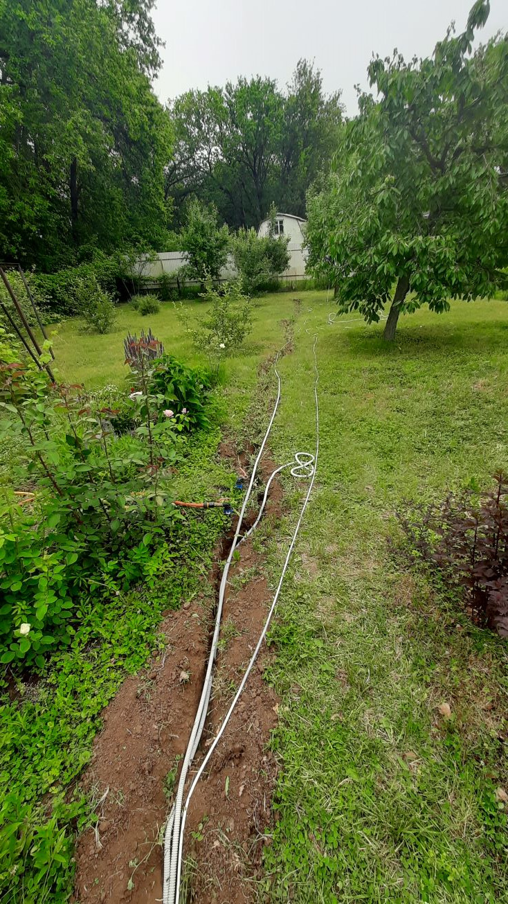
I struggled with pulling the cable through the corrugation until I watched a video from a professional on YouTube. Finally, the cable laying was done. The next stage is installation of a box with relay automation, connecting the controller and commissioning. Colleagues at work joked – call us for commissioning! But all these steps went without a hitch, so there was no need to call anyone. And here is the first launch! Hastily connecting one valve, gave the command to open from the laptop, turned on the pump with the command… The water started pouring out! This was confirmed by the feedback signal from the flow sensor. Success!
Then I installed everything thoroughly, including the other two valves. I connected the sprinklers. I turned on the pump again, gave a command to the valve, and… Water flows, but the pressure is weak, barely enough to irrigate a couple of square meters around each sprinkler. What nonsense?! I tried another valve – the same thing. According to the plan, two of the three valves should be open at the same time. In manual mode, the pump performance is just enough to effectively provide flow from two sampling points. And here… even one point is not enough. I unscrewed the “horns” – the splitter – from the valve, and tried to let the water flow through only one sprinkler, as was intended from the very beginning. It works a little better, but still the spray area is too small.

I began to look for the cause, and soon found out that the problem was in the flow sensors. The sensing element inside blocks the lumen too much and limits the flow of water through the sensor. For applications where high flow rates are not required this is acceptable, but not for normal sprinkler operation. And how wonderfully everything was planned! Feedback from every actuator! Alas, I had to abandon it. I removed the sensors and the sprinklers worked as expected.
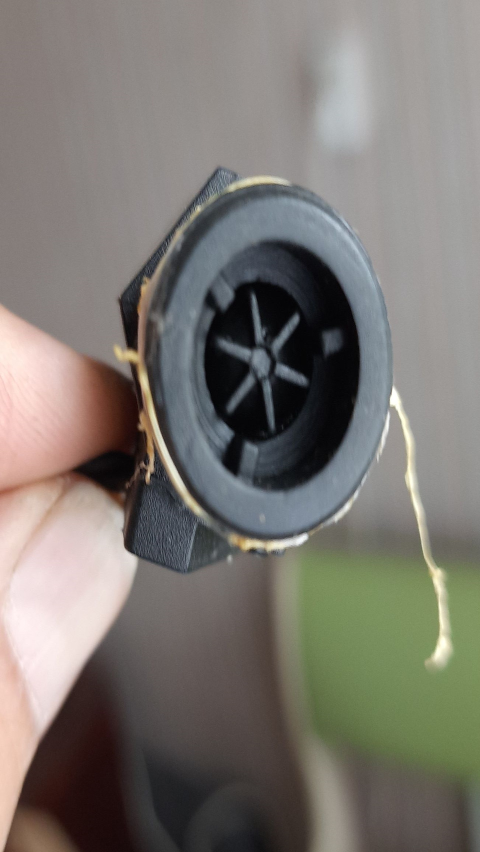
However, what about feedback? How do I know if the pump is working and if water is flowing through the pipes? I had to return to the original, back in February, idea – to use a temperature sensor to control flow. The water from the well is cold – no higher than 13 degrees. This means that by measuring the temperature of the pipe, I can understand that if the pipe becomes cold, then the pump is turned on and pumps water. So I did.
“Towards the end” I checked the work via SMS commands – everything works perfectly! Although SMS sometimes go through with some delays.
In this state, the system met the summer season and was “put into trial operation.”
To be continued.


