how I started collecting quantum circuits
Quantum computing is a beautiful, complex, new world, but we don’t have to wait for developments from Silicon Valley to start experimenting ourselves. In fact, there is a little-known, but quite affordable way to build a quantum computer yourself.
In 2000, scientists Knill, Laflamm and Milbourne developed a method for performing quantum computing, which was later called the KLM protocol. In fact, they discovered the possibility of performing any theoretical quantum calculations with the help of simply well-built optics, in particular, mirrors.
Using the quantum properties of light and the KLM protocol, we can quickly and inexpensively create qubits using off-the-shelf optical components and electronics. Beam dividers available for only ~$20, which makes the KLM protocol the cheapest method to implement a quantum computing device. This accessibility allowed me to study this technology right at home.
▍ Quantum Randomness
To us, the actions of quantum systems look “naturally” random. The actual action of a subatomic particle is determined by the probability of that action occurring when it is observed, making this technology well suited for generating randomness and entropy.
In this regard, the first quantum circuit I assembled was a simple random number generator based on the KLM protocol. A beam splitter can create two different optical paths or states of a photon based on its polarization. This possibility is determined by the fact that the beam splitter reflects horizontally polarized light without interfering with the flow of vertically polarized light.
This in itself is not particularly interesting, but light also has another feature known as superposition, where a photon can act either as a particle moving along one of two paths, or as a wave moving along both at the same time. This effect was first observed by Thomas Young in his famous double slit experiment.
And it is here that a strange phenomenon occurs. If the photon, when passing through the beam splitter, is not perfectly polarized horizontally or vertically, then it will simultaneously be reflected and pass through the slit. And only when a photon is detected, it “collapses” from a wave-like state back into a particle, ending up randomly in one of the states.
Confused? I recommend the video below by physicist Yevgeny Khutoryansky, in which all this is explained much more clearly and interestingly.
▍ An explanation of quantum mechanics
▍ Light measurement
If you arm yourself with the knowledge described above, then it will not be difficult to create a quantum device. We will pass a beam of light through a beam splitter and measure it. But how do you measure light?
The answer is simple. Despite the existence of high-tech (and expensive) equipment for measuring photons, the easiest way to measure light is with a photoresistor.
The essence of the photoresistor is that it allows you to change the resistance of the circuit based on how many photons have come into contact with it. When the photons reach its surface, the resistance of the circuit decreases and the voltage in the circuit rises.
Photoresistors are on par with transistors and LEDs, making them a very affordable component for DIY quantum devices.
▍ A little about the states of photons
In our quantum computer, linearly polarized photons will be used as qubits. This gives two possible states of the qubit: horizontally polarized and vertically polarized, as well as a superposition, which can be any angle between 0 and 90°. Briefly, these states are shown below in text form:
- vertically polarized light:
| - horizontally polarized light:
__ - superposition:
/
▍ Development of a quantum circuit
When designing quantum computers, everything starts with an algorithm. You need to know exactly what the quantum circuit needs to do before you can manipulate the particles to get what you want.
For our first quantum circuit, the algorithm will be very simple:
- Apply a pulse to the laser diode to generate photons.
- Pass these photons through a beam splitter.
- Measure the states V and H of the photons leaving the splitter using photoresistors.
- If the H voltage is higher (lower resistance, more photons) than the V state, return 0.
- Otherwise, return 1.
- If the voltage is equal, repeat the algorithm.
Now we can move on to creating our quantum random number generator.
▍ Arduino Firmware
/* Annotated QRNGv1 Firmware V1.1
* Author: Noah G. Wood
*
* Copyright (c) 2019 Spooky Manufacturing, LLC
* License: GPLv3.0
*
*/
int triggerPin = 2; // Этот пин будет создавать импульс в квантовой схеме
int hPin = A0; // Этот пин измеряет горизонтально поляризованные фотоны
int vPin = A1; // Этот пин измеряет вертикально поляризованные фотоны
float H = 0;
float V = 0;
void setup() {
// Установка triggerPin и последовательного подключения
pinMode(13, OUTPUT);
pinMode(triggerPin, OUTPUT);
Serial.begin(9600);
}
int Random() {
// Подача импульса на лазер
digitalWrite(triggerPin, HIGH);
delay(3);
digitalWrite(triggerPin, LOW);
// Считывание фоторезисторов
H = analogRead(hPin);
V = analogRead(vPin);
// Определение случайного бита
if(H>V) { // Если фотонов больше в состоянии H, вернуть 0
return 0;
} if(H < V) { // Если фотонов больше в состоянии V, вернуть 1
return 1;
} else {
/* Одинаковое число фотонов в обоих режимах.
На самом деле нередкий случай. Для наших целей мы просто
будем выполнять функцию рекурсивно, пока не сгенерируется случайный бит
*/
Random();
}
}
void loop() {
// Основная программа
// Запуск программы и вывод случайного бита на последовательный порт
Serial.print(Random());
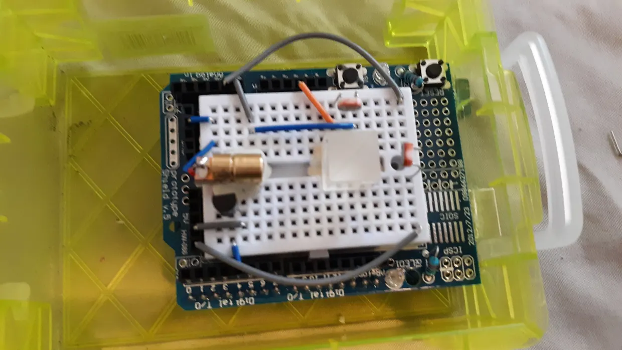
}▍ Optical design

Optical design: laser diode directed at the beam splitter. Each output path of the divider is directed to a separate photoresistor, the characteristics of which are measured using the Arduino Uno
▍ Required Components
If you want to assemble all this yourself, then here is a list of what you need (I used these exact components):
- Arduino Uno;
- photoresistors;
- beam splitter 50/50;
- red laser LED 650nm;
- plasticine;
- Arduino Breadboard Shield
- case (in this case I ordered it, but in the first prototypes I just used cardboard boxes)
About the delivery of beam splitters:
Delivery of beam splitters may be delayed, as they come from China. I would advise ordering these components in Edmundbut we don’t need to use such expensive laboratory-grade equipment in our home experiments – yet.
Tips:
- use a small plasticine ball to mount the breadboard and laser diode;
- put on cotton gloves so as not to stain the optics;
- cover the device during use to block out external light.
▍ One photon problem
For this project, you can use a laser pulse consisting of trillions of photons. Simply by measuring both “states” and comparing the voltage offset, one can easily determine what value the collapsed qubit should give. However, for more advanced projects involving quantum entanglement (which is where the whole power of quantum computing lies), it is necessary to use – the so-called sources of a single photon.
Unfortunately, it is not so easy to implement reliable generation of a single photon. The same quantum randomness that promises us a potential far beyond that of digital computers also governs the creation of photons. And that is why there is not yet an ideal source on the market that generates them one at a time, although promising research has already been done with nano-diamonds, which can lead to the creation of affordable commercial quantum computers.
However, by attenuating the laser beam, it is quite possible for an amateur to create a sufficiently reliable source of single photons for his own use, but this solution is not ideal and carries its own difficulties.
▍ Creating Entangled States
Entanglement is another big problem when creating your own optical quantum circuits. After all, photons don’t interact with each other – how can they get entangled? But the same geniuses (seriously, geniuses) who developed the KLM protocol also found a way to use simple optical components to entangle photons with non-linear phase-shift gates, and I know it sounds like science fiction: teleportation.
To be honest, I don’t fully understand either principle. If you are interested in learning more about this, please contact Wikipedia page (English)dedicated to the KLM protocol. I personally work on this in my home workshop, but so far I have not achieved anything.
▍ Open Quantum Computing Projects
My fascination with quantum computing, which led me to build my own quantum computer, also led me to launch Spooky Manufacturing, an open source quantum computing startup.
At the moment we are running repository on GitHubwhich provides complete instructions, diagrams and software for those experimenting with this technology (all under the open license GPLv3).
I invite those who wish to also get acquainted with other projects. We currently have two tools in development:
- QEDA: software for automating the development of optical circuits;
- QController: a program for testing quantum circuits.
We hope these tools make designing, building and programming homemade quantum computers as easy and fun as working with an Arduino or a Raspberry Pi.
This article is written to the best of the knowledge of the author. All of its content is for informational or entertainment purposes only and does not constitute personal advice or professional advice for financial, legal, technical or business purposes.