Flipper Zero – pre-final parts for molds, getting ready to start production

Flipper Zero – a project of a pocket multitool for hackers in the Tamagotchi form factor, which we are developing. Previous Posts [1],[2],[3],[4],[5],[6],[7],[8]
Flipper’s body is made up of 11 (sic!) Plastic parts that will be made by injection molding. This is the most efficient way to get quality parts in mass production. To do this, first, molds are made for each part (or group of parts). As a rule, each mold consists of two main generators and many auxiliary parts and mechanisms. Plastic will be fed into the cavities in the mold under high pressure through channels inside the mold.
Now we are working on a project with a casting factory that will mass-produce cases. In the article, we will show how we specify parts, based on this information, the manufacturer develops forms and builds technological processes for the production of each of the parts.
Molds (molds)

An example of a mold, photo from the site tleda.ru
There are many ways to make a device case: milling, 3D printing, silicone molding, etc. But all of them are not optimal for mass production, when tens and hundreds of thousands of parts need to be produced. In our case, the only acceptable option is injection molding. This method allows a large number of parts to be produced as quickly as possible with an overall low cost and high repeatability.
The process is broken down into two main phases: making the casting tooling and the batch casting process. Tooling is made on EDM machines, then polished and / or textured by etching or laser. The cost of making one such mold is thousands of dollars, and the cost of making a mistake is high, both in terms of money and time. Therefore, we carefully check the body parts before starting the production of molds.
Top cover
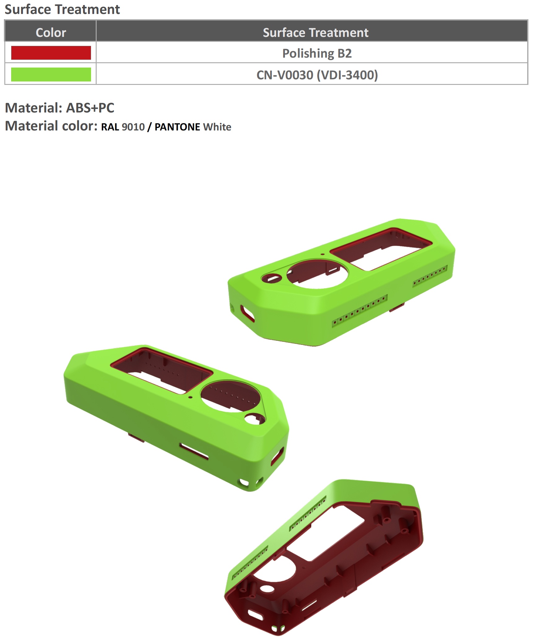
Flipper Top Cap
Ignore the colors, different surface textures are shown here with different colors. Light green shows shagreen – a slightly rough surface. Marking CN-V0030 means the grain of this very shagreen, that is, how rough the surface will be. Dark red – smooth surfaces.
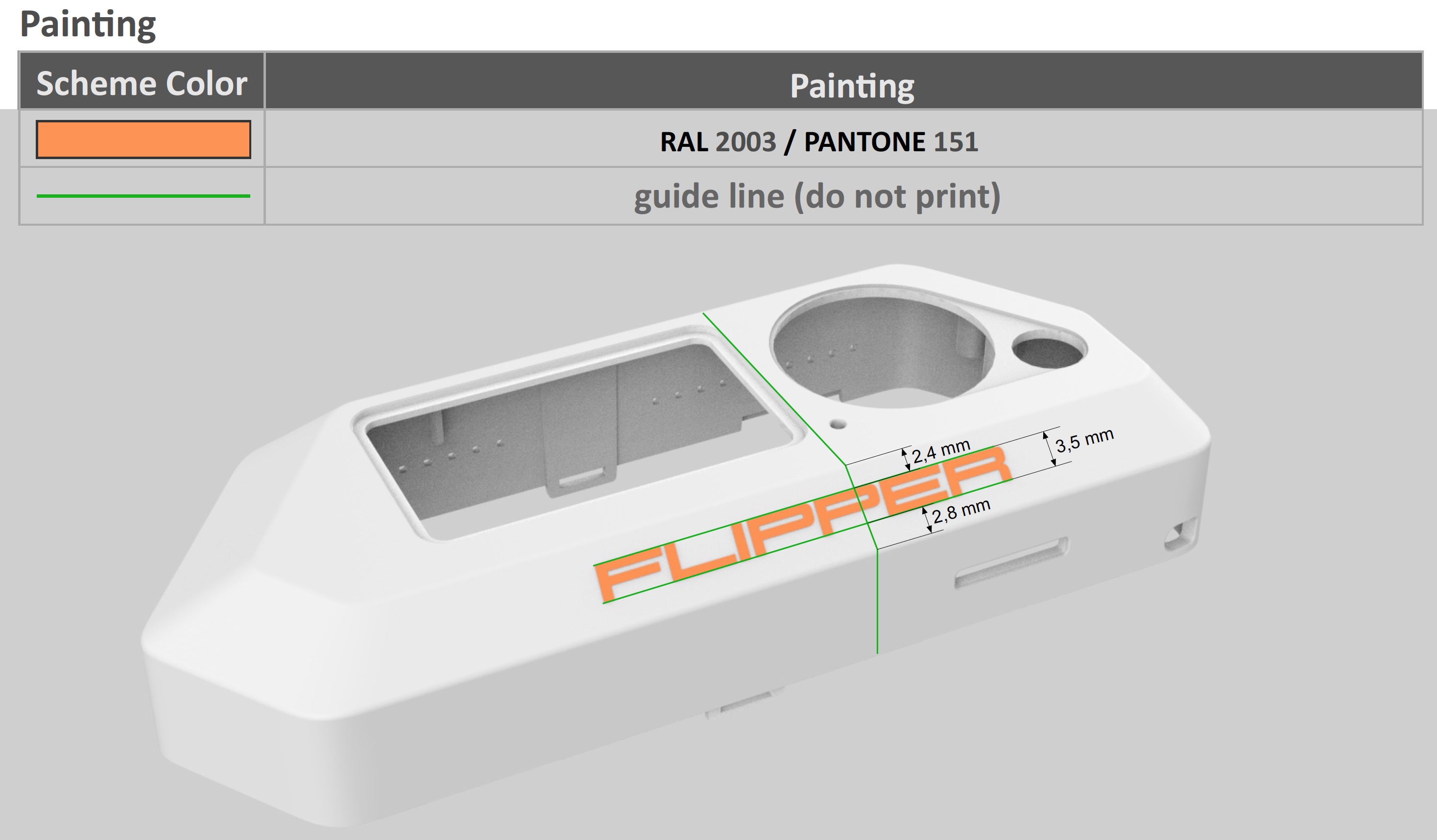
The logo on the top cover will be silk-screened.
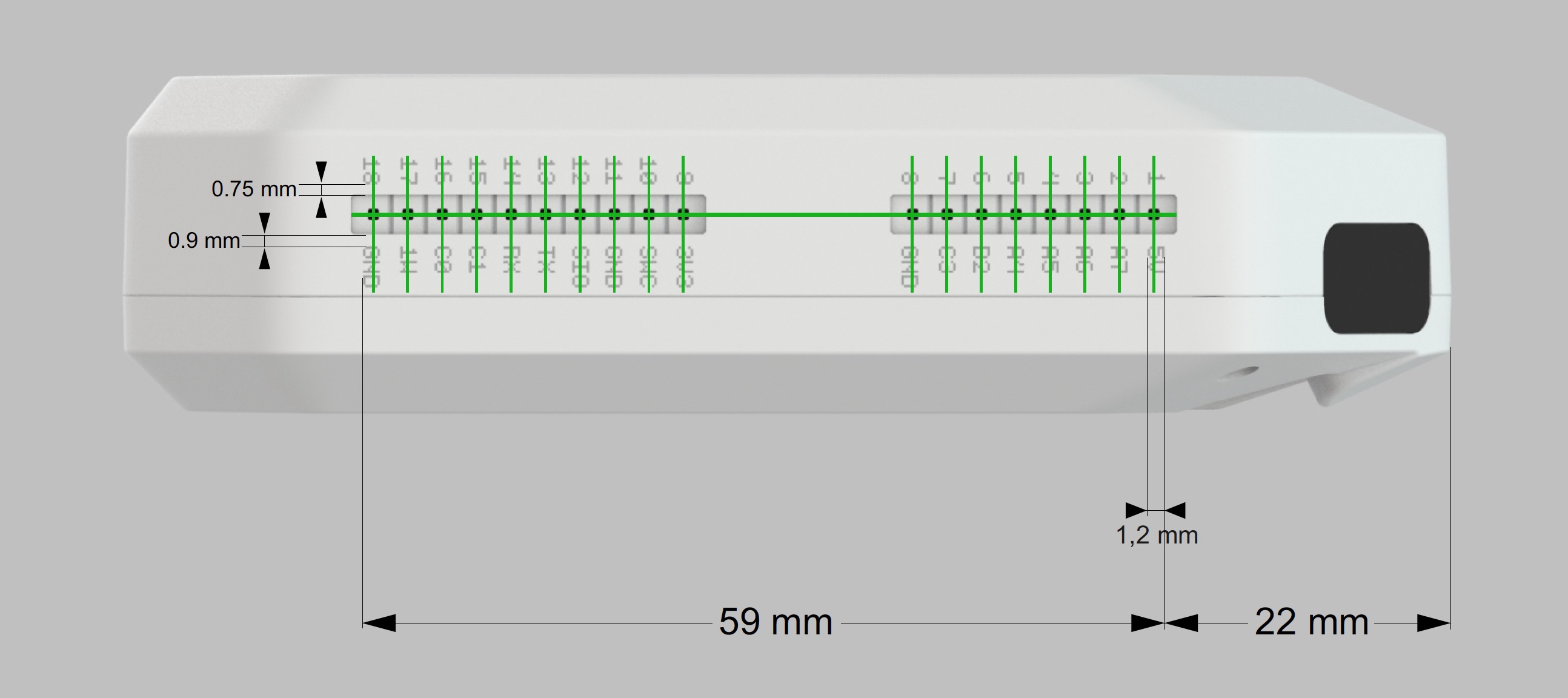
External GPIO marking by laser engraving
The signatures for the GPIO comb will be laser engraved. Because of the small characters, silk-screen printing in this case gives less contrast and readability.

SD card marking
In order to understand which side to insert the SD card (in which direction the corner), we decided to add an icon. It will also be applied with a laser.
Screen Protector
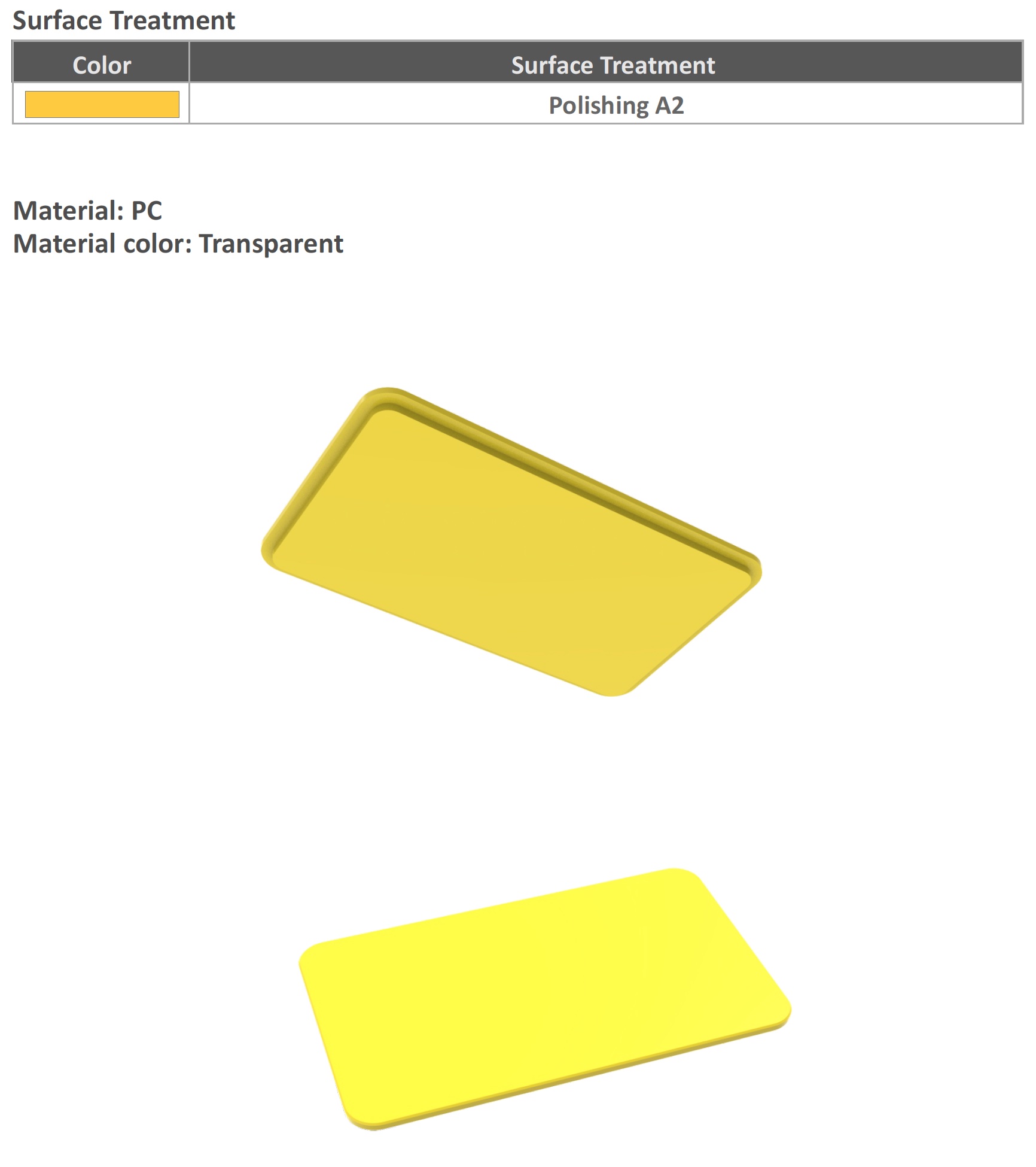
Screen window protects from direct contact with the screen glass
This “glass” is inserted between the display and the top cover. It will protect against direct contact with the display. Its surface should be perfectly smooth.
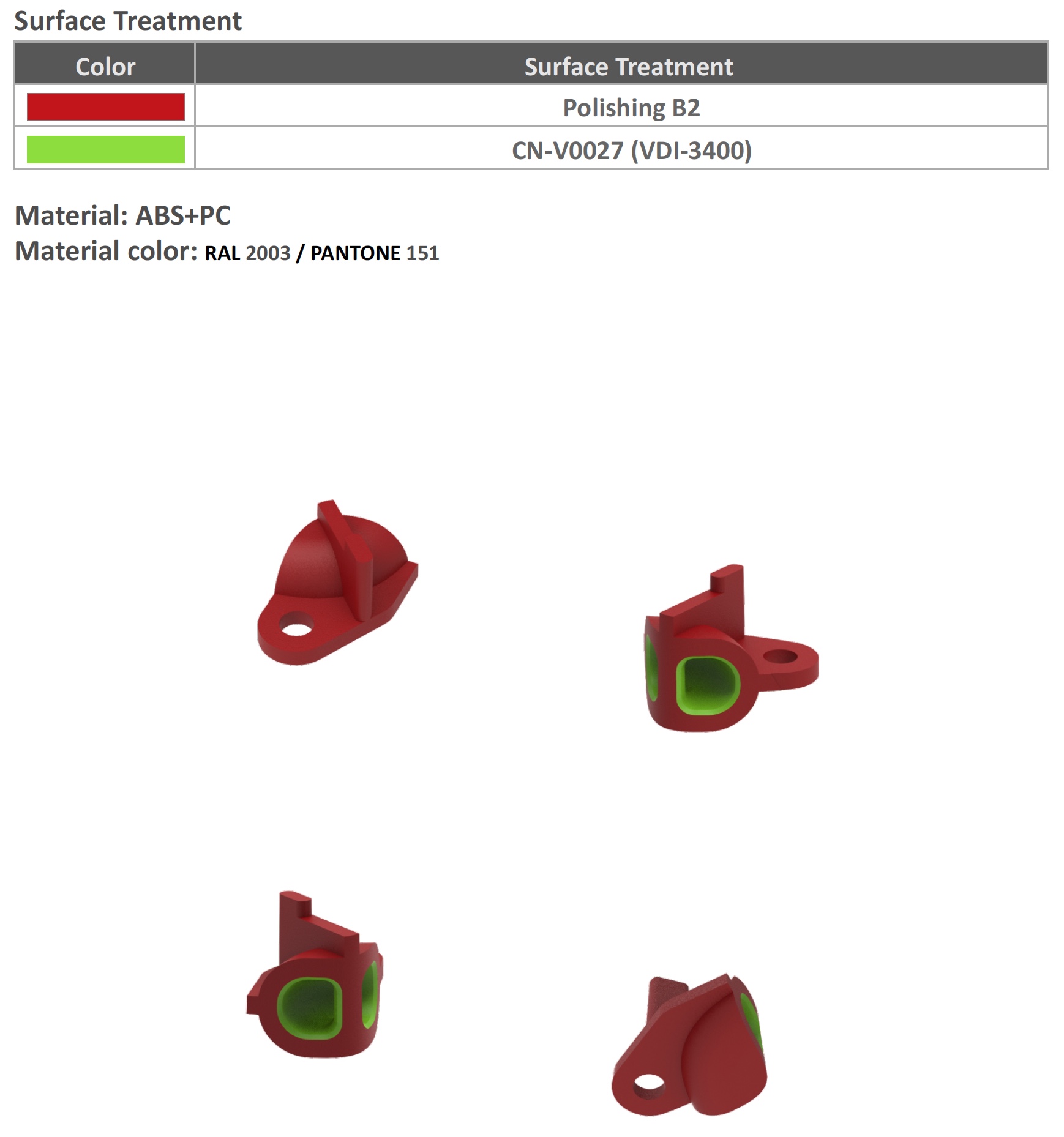
Light guide for status LED

The light guide outputs the light of the SMD LED on the board to the surface of the case
The status RGB LED is located deep in the case – on the board. In order for the light from it to be visible on the surface, a plastic tube abuts against it – a light guide through which the light goes up. It also “mixes” different RGB colors for uniform intermediate colors such as white or yellow.
The location of the fiber in the housing
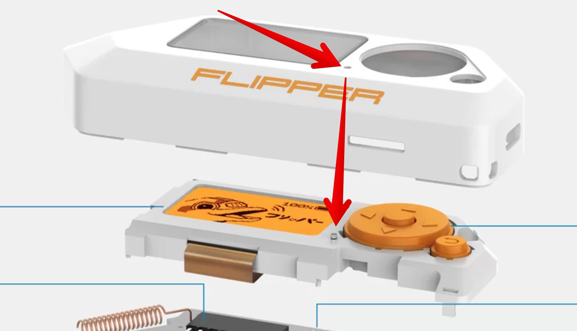
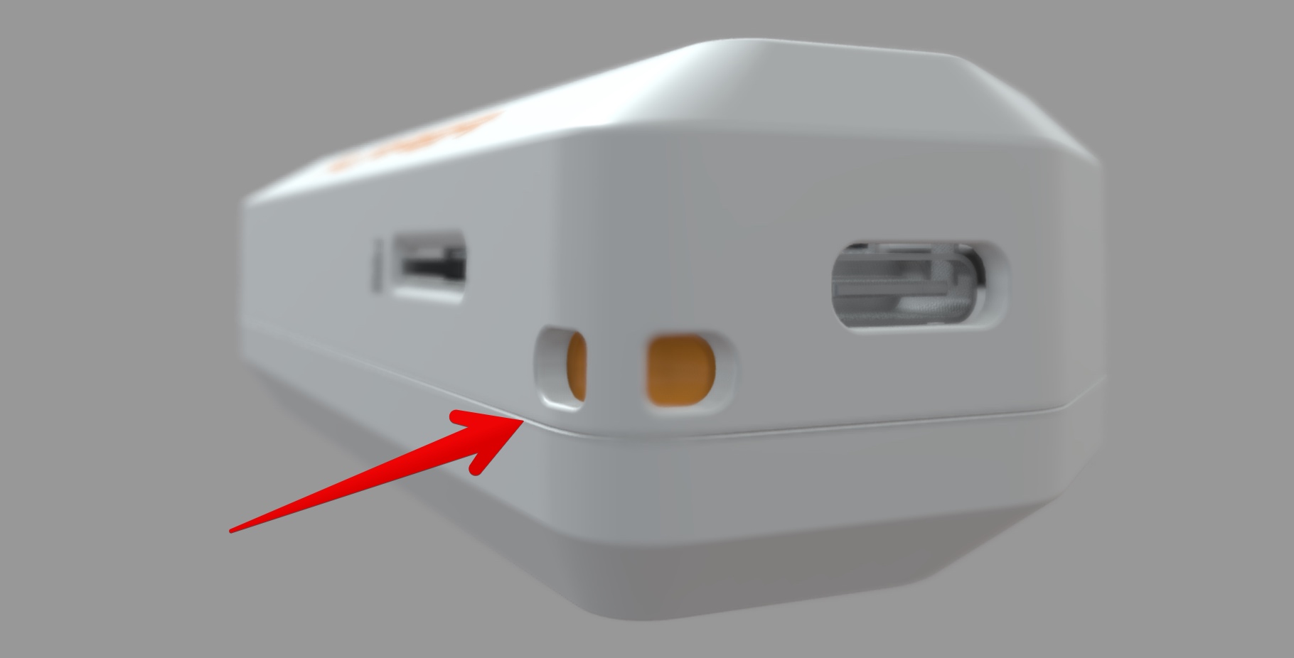
Infrared port window
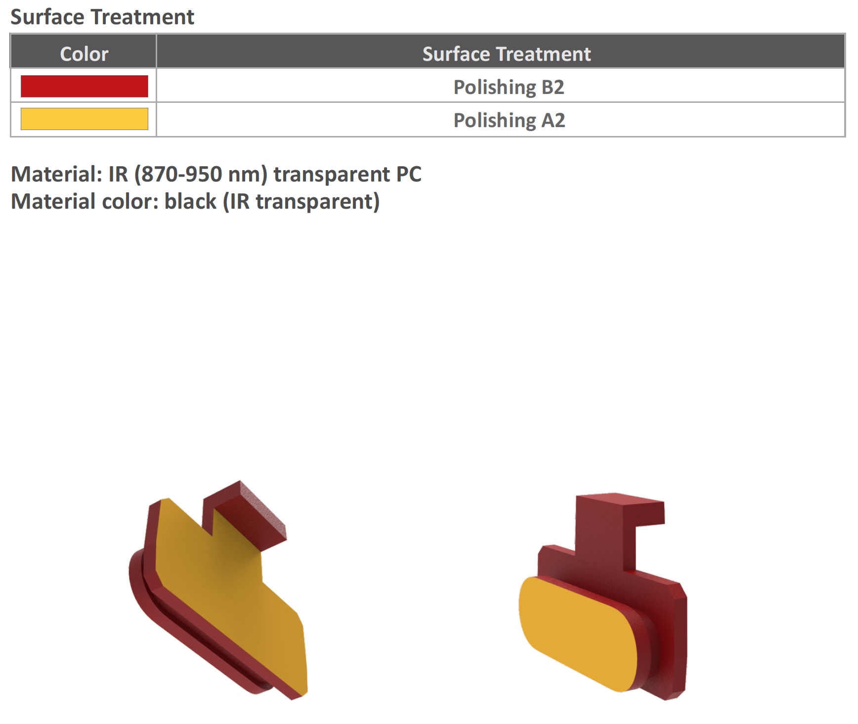
The black window of the infrared port only allows the infrared spectrum to pass through
The infrared port is covered with a dark red window, the material of which cuts off visible light, but is transparent to the infrared spectrum. In addition to the decorative function, this filter improves the quality of the IR signal reception. The same plugs are on your TV remotes.

Infrared port location
Buttons
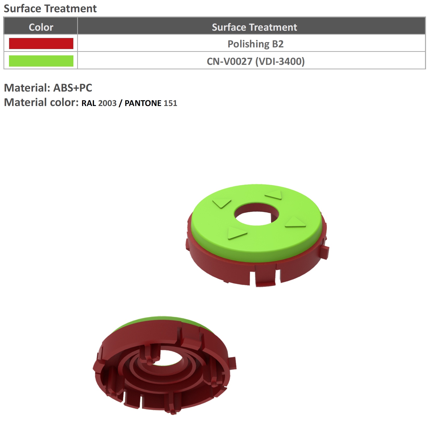
Detail of 5-way joystick
There are only three button details: joystick circle, center insert and back button. They are assembled into a rig and are spring-supported for a more elastic stroke.
Reinforcement strap insert
The insert takes the load of the strap
There is a strap hole on the side of Flipper. To prevent the entire load of the strap from taking on the thin partition of the outer cover, a separate insert is made. This increases the peel-off load by several times. We will give specific figures for the withstand load later, when the casting in the final material is ready.
Grille hole
Frame of buttons and screen

Snap fixes screen and buttons
This part positions the screen, distributes the load to the top cover and screen window, and acts as a cradle for spring buttons.
Insert between battery and RFID
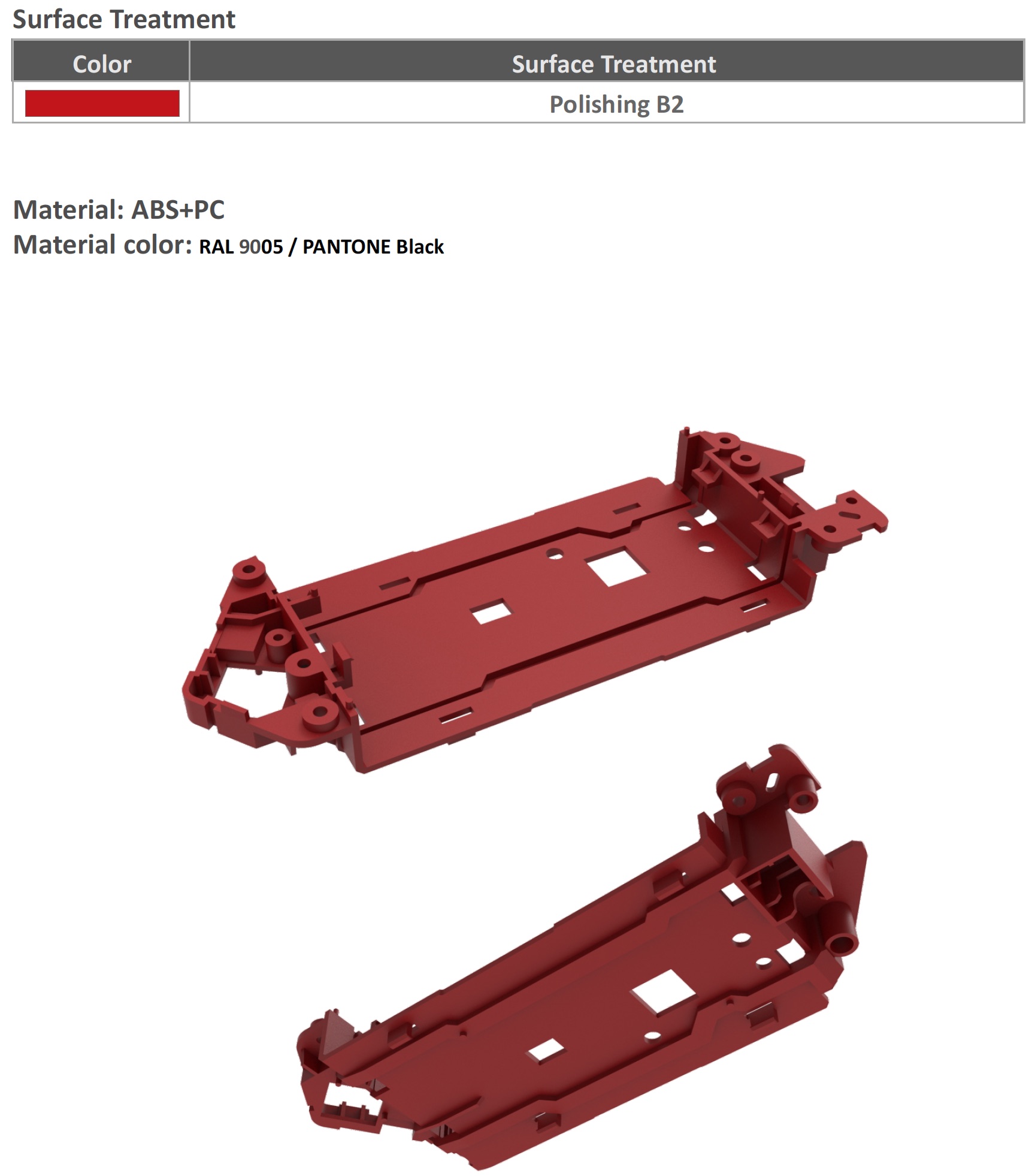
Insert supports battery, positions board with iButton and infrared port
Insert location in device
This part is inserted into the lower part of the case between the battery and the RFID board and performs many functions: it positions the battery, fixes the RFID and iButton loops of the board, and the iButton + IR board is fixed on it.
Bottom cover
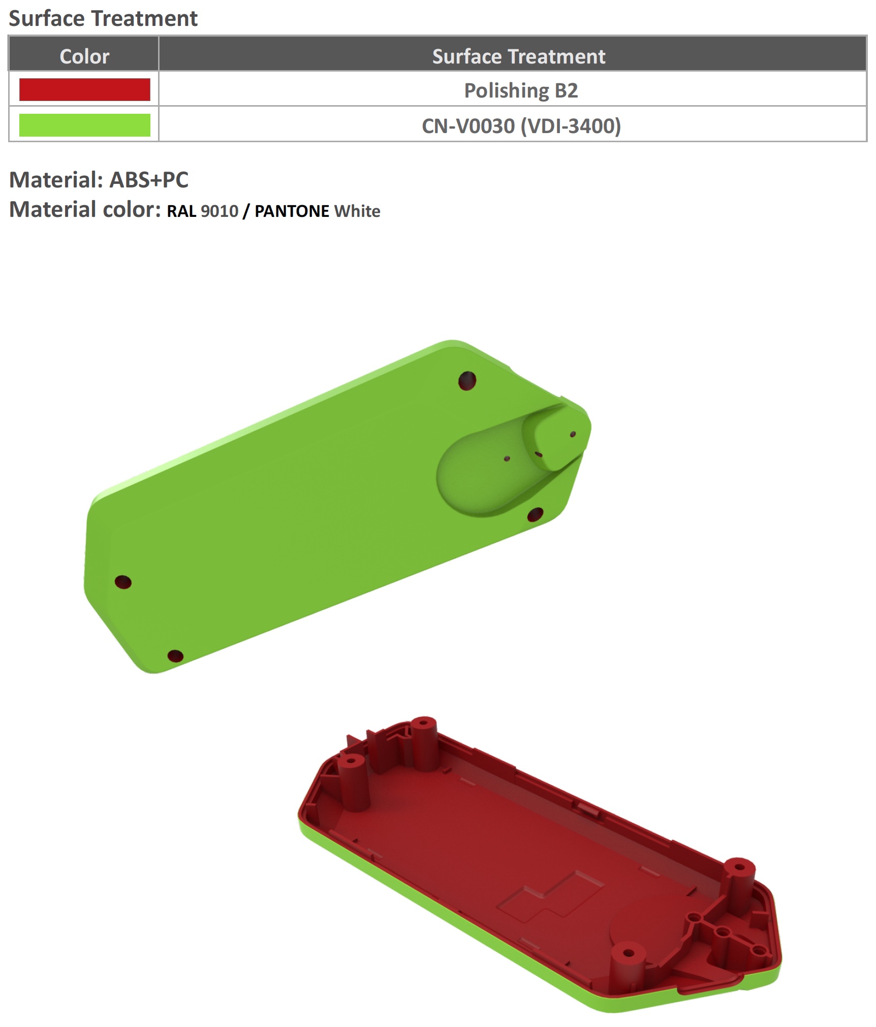
The bottom cover has an iButton pad and screw holes.
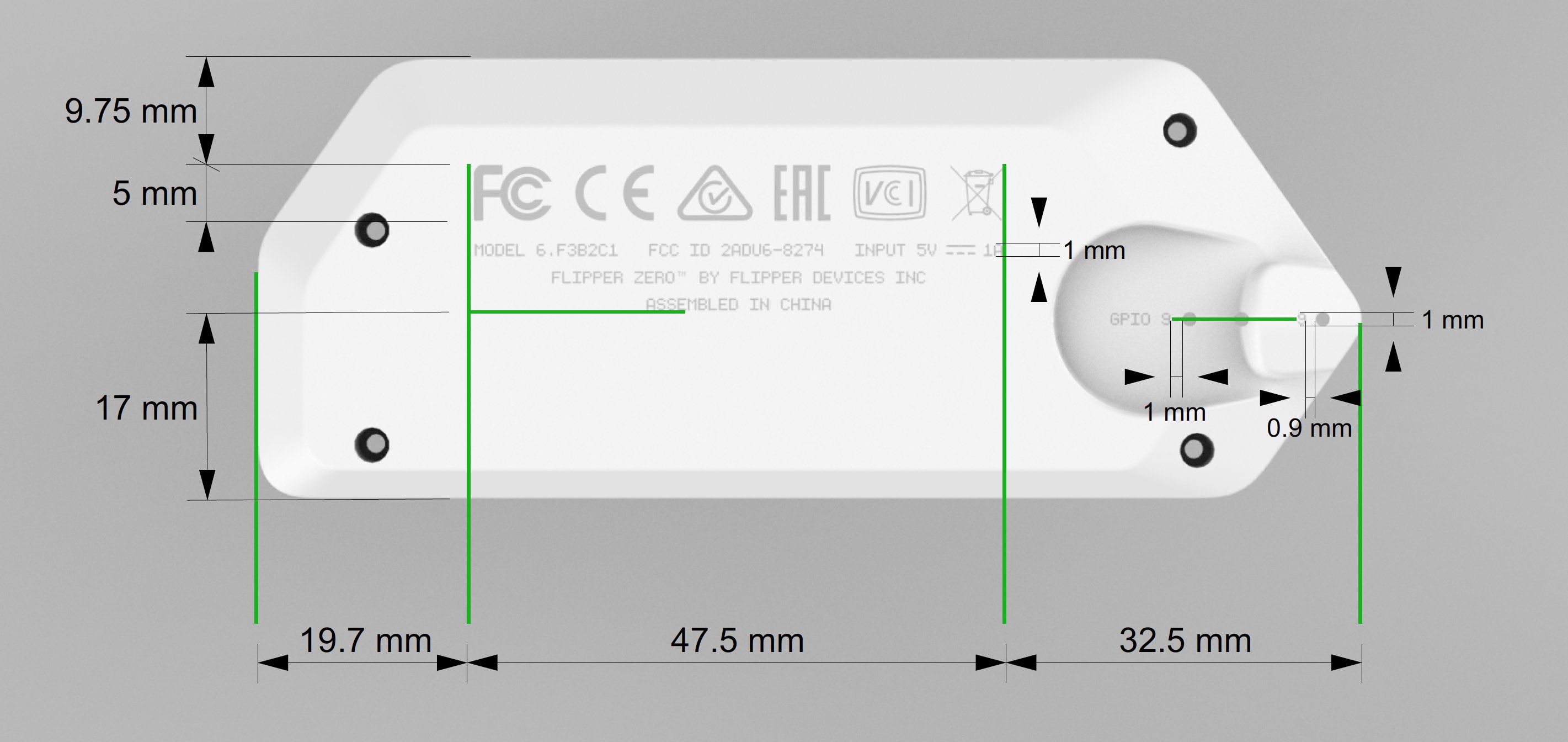
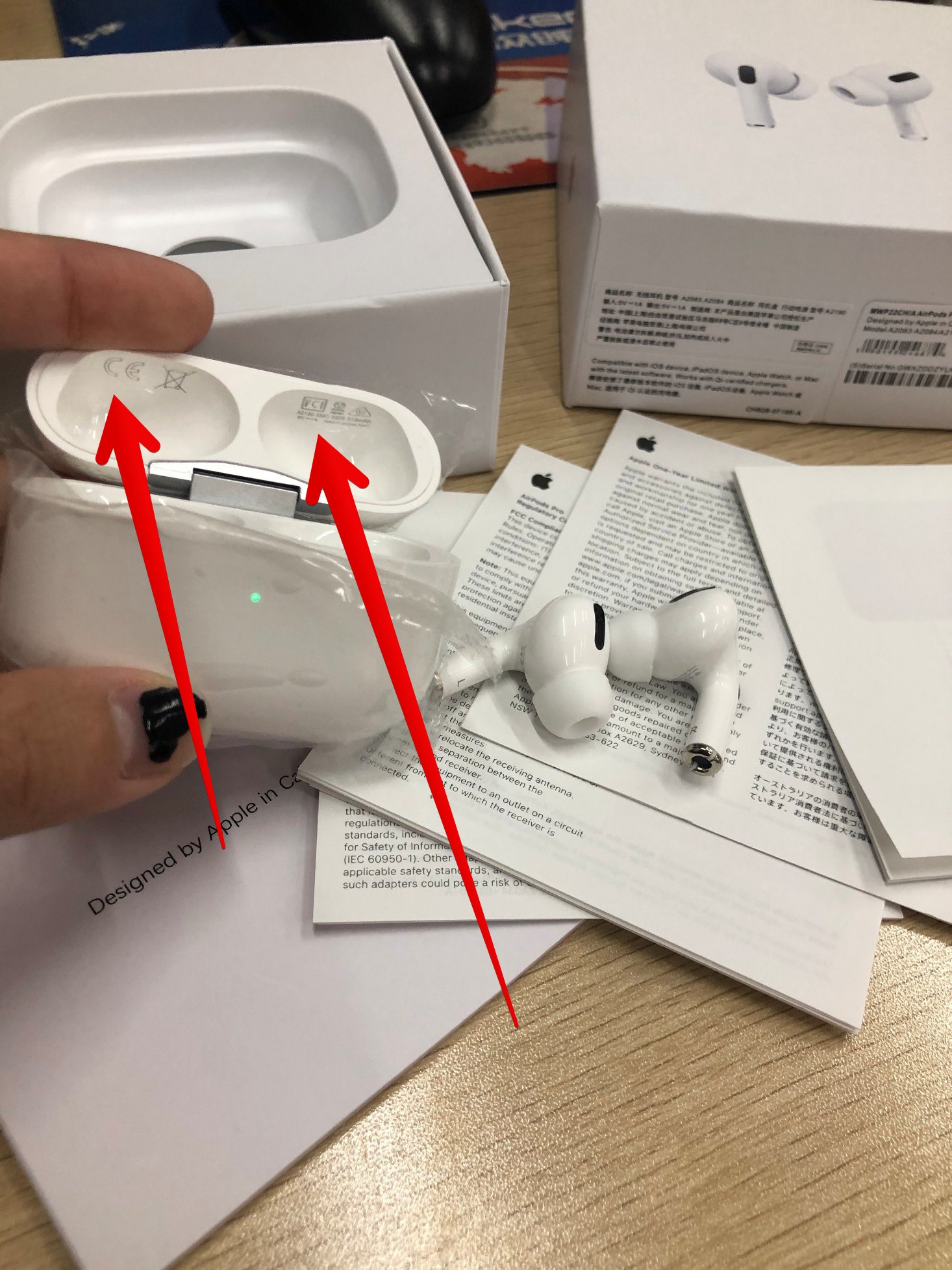
The markings on the bottom are shown as an example. Unfortunately, you can’t get rid of it and make it smaller, too; certification requires a strictly defined size. It’s funny how some companies hide these icons in the weirdest places for aesthetics. For example, in Apple AirPods headphones, these icons hidden inside hinged cover. We do not have such hidden surfaces, so we will have to apply to the bottom cover. What witty inscriptions would you recommend to put next to Assembled in China?


