connecting lines in SVG

This article describes a way to implement connecting lines between SVG objects. Connecting lines are automatically rearranged when the position of objects is changed. Along the way, the OnParametersSet method is considered.
Previous article “Blazor WebAssembly: Drag and Drop to SVG”.
What will happen in the end
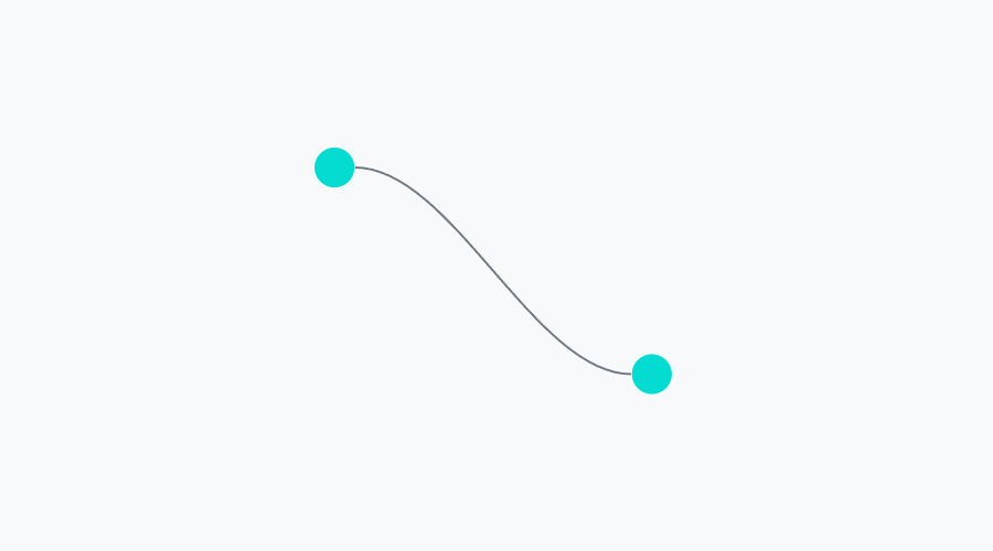
The result is a Blazor Connector component. Usage example:
<svg xmlns="http://www.w3.org/2000/svg">

    <circle cx="85" cy="100" r="15" fill="#04dcd2" stroke="#fff" />
    <circle cx="315" cy="250" r="15" fill="#04dcd2" stroke="#fff" />
    <Connector
        X1=100 Y1=100
        Dir1=Direction.Right

        X2=300 Y2=250
        Dir2=Direction.Left />

</svg>
Listing 1. Using the Connector Component

Connector accepts input
coordinates of the start and end point,
direction of entry to the point: top, right, bottom, left.
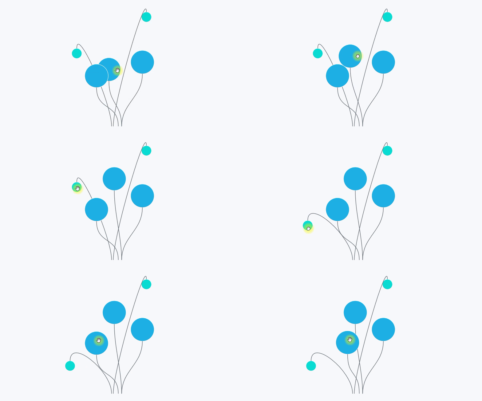
At the same time, when the input parameters are dynamically changed, the Connector rebuilds the connecting line (see Fig. 1).
If you just need a ready-made solution, you don’t need to read the article – copy the code of the Connector component from GitHub.
Main idea
SVG has a built-in ability to draw smooth lines – the Path element. Path supports various options for drawing lines. For connecting lines, the cubic Bezier curve implemented in Path is suitable.
To draw a cubic Bezier curve, you need 4 points (Figure 3):
start point, end point,
start pivot and end pivot.

The shape of the curve depends on the position of the control points. In Figure 4, the first anchor point is lifted up.

Blazor Component Connector
Listing 1 shows the use of the Connector component. The Connector appears on the page as an SVG path element.
<path d="M @X1 @Y1 C @c1x @c1y, @c2x @c2y, @X2 @Y2" />

@code {
    [Parameter] public Direction Dir1 { get; set; } = Direction.Right;
    [Parameter] public double X1 { get; set; }
    [Parameter] public double Y1 { get; set; }

    [Parameter] public Direction Dir2 { get; set; } = Direction.Left;
    [Parameter] public double X2 { get; set; }
    [Parameter] public double Y2 { get; set; }


    // reference points

    double c1x;
    double c1y;

    double c2x;
    double c2y;
    …

    public enum Direction {
        Top,
        Right,
        Bottom,
        Left
    }
    …
Listing 2. The Connector Component.
When drawing connecting lines:
the start and end points (X1, Y1; X2, Y2) (marked in blue in Fig. 3) are specified,
pivot points (c1x, c1y; c2x, c2y) (marked in red in Fig. 3) need to be calculated.
Let the connector line only approach the point from 4 sides (see the enum Direction in Listing 2):
above,
on right,
from below,
left.
Let’s calculate the anchor points for the connections on the left and right.

If the connection is “on the right” (in Fig. 5, the connecting line approaches the upper blue point on the right), then the coordinate of the anchor point along Y is equal to Y1 (c1y = Y1). The X coordinate depends on X1: c1x = X1 + 70.70 is an arbitrary factor chosen by eye.
Pivot points for top and bottom connections are calculated by analogy.
See GitHub for the algorithm implementation code.
Dynamically rebuild the connector when parameters are updated. OnParametersSet method
When changing the values of the input parameters, the Connector must recalculate the reference points c1x, c1y; c2x, c2y.
A signal (event) for recalculation can be a call to setter input parameters – Listing 3.
...
@code {
    [Parameter] public Direction Dir1 {
        get { ... }
        set { ... calc(); };
    } = Direction.Right;

    [Parameter] public double X1 {
        get { ... }
        set { ... calc(); };
    }

    [Parameter] public double Y1 {
        get { ... }
        set { ... calc(); };
    }
   ...
Listing 3. The Connector Component. Recalculation of control points in sets. Not the best option.
This is not the best option. Let’s say the parameters of the Connector-ora are changed all at once:
<button @onclick=Update>Update</button>
<svg xmlns="http://www.w3.org/2000/svg">

    <Connector
        X1=X1 Y1=Y1
        Dir1=Dir1

        X2=X2 Y2=Y2
        Dir2=Dir2 />

</svg>

@code {
    Direction Dir1;
    double X1;
    double Y1;

    Direction Dir2;
    double X2;
    double Y2;

    void Update() {
        Dir1 = Direction.Left;
        X1 = 100;
        Y1 = 100;

        Dir1 = Direction.Right;
        X1 = 200;
        Y1 = 200;
    }
    ...
Listing 4. Updating Connector props at one time
The setter will be called for each input parameter, i.e. the Calc method will be called 6 times.
You can work around this problem using OnParametersSet.
...
@code {
    [Parameter] public Direction Dir1 { get; set; } = Direction.Right;
    [Parameter] public double X1 { get; set; }
    [Parameter] public double Y1 { get; set; }
    ...
    protected override void OnParametersSet() {
        calc();
    }
    ...
Listing 5. The Connector Component. Calculation of control points in the OnParametersSet method
For Listing 4, the OnParametersSet method will be called once.
OnParametersSet is used not only for such cases, more details in the documentation Avoid unnecessary rendering of component subtrees…
The Connector is ready. Using the Connector and Draggable from the previous article, you can make underwater plants, or IKEA lights – Fig. 1.


