CAN bus based smart sound sensor receiver design concepts
– The sensors are passive.
A more correct phrase would sound like this: “Data from sensors in automated control system software systems are passive.” But this is long and difficult to say.
In response I hear:
– What did you say?! Repeat.
I repeat, not expecting the professor’s subsequent violent reaction. Figuratively, what happened next can be described as follows: we were sitting, calmly playing chess, and suddenly the professor takes out a stick and turns the game into emotional hockey.
He began to energetically scribble the manuscript, uttering spells in his hearts:
– After this phrase, you are not my colleague… This is elementary illiteracy… Don’t come to me again…
I remained calm because… was confident in the correctness of his thoughts, remained at the “chessboard” and simply looked in surprise at the “hockey field”, where the professor, in a manner unusual for him, “pounded the ice with his stick.”
A minute later the professor cooled down as suddenly as he had flared up. Then it dawned on me that we simply had different perspectives on the problem: the professor had a classic analog control circuit, and I had one mediated through software.
Nevertheless, the conversation was crumpled. I packed up and left. On the way home, I finally came up with options for the ACS scheme. I laughed and immediately called the professor on his cell phone right from the street. Continuing to laugh, I tried to explain on my fingers the reason for the aberration of our view of sensors. It seems that the difference in our approaches also began to dawn on him: he has an analog circuit with wires, and I have a software environment with registers.
As a result, I got a classification of automatic control systems, consisting of 3 basic circuits, which I dare to talk about here before moving on to the description of the audio data receiver device in the next article.
2 Basic schemes for receiving and processing data from ACS sensors.
2.1 Analog circuit for data transmission and processing
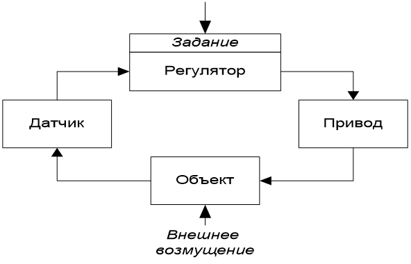
We will analyze ACS circuits using the example of the implementation of a control regulator, starting from the classical diagram of the control cycle shown in Rice. 1.
Traditionally, the control circuit is based on an analog control circuit. Exercise combined with the regulator block, because masters are actually included in the equipment. The connection arrow from the sensor to the regulator shows that the sensor in relation to the regulator is an active element, and the regulator acts as a passive element.
The drive elements and the controlled object play traditional roles here and do not need commentary.
2.2 Scheme for obtaining and processing data in traditional ACS technology
The scheme for obtaining and processing data in traditional ACS programming technology is shown in Rice. 2
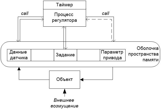
The automated control system scheme has undergone significant transformations. Between the controller process and the Object there is a shell for accessing the memory space. The architecture of the memory space can be different: from distributed across local hive controllers to consolidated on the OPC server. This is not important. It is important that the data, after generation, goes directly into RAM or the database, where they await their processing queue. For uniformity and convenience, I also placed the task in the diagram in the general memory space.
The diagram does not detail the mechanisms for the memory space to receive data from Sensors and transmit parameters of Drives – behind this there is now a whole industry of interfaces and levels of automated process control systems. The main thing is that the interaction between the Object and the Regulator is now carried out indirectly through elements of passive memory.
The controller does not interact directly with sensors and actuators. To obtain sensor data, the controller accesses the memory space registers through a shell call, and the shell already returns the result. Likewise, to influence the drive, the controller also calls the shell function. This function can return an empty result (void), as indicated by the dotted arrow (Rice. 2).
The described controller can be implemented in any modern universal language: C++, Python, Java or in a specialized DSL, and access to sensor data is carried out using the appropriate API library, for example, Modbus.
For our classification, it is important to note that in an automatic control scheme based on traditional procedural programming, the nature of the interaction between the controller and the sensor changes: the controller becomes active in relation to sensor data, and the sensors themselves are covered by a passive proxy of RAM or database.
2.3 Scheme of data transmission and processing when implementing an event-oriented approach
A legitimate question arises: “Is it possible to implement a software control controller using an analog circuit in which activity is returned to the sensors?” It turns out yes. Over the past 20 years, technology has been successfully developing in the West. processing data in a streamwhich is also called event-driven approachbriefly denoted by the acronym EDA (Event Driven Architecture).
There are many corresponding programming tools available for programming in the EDA approach. [1,2,3]. For Python, there are many popular libraries for implementing EDA [4]. Personally, I prefer the implementation of data processing in a stream based on a functional programming language, for example, Elixir [5]which inherits the built-in message sending mechanism from Erlang.
Let's consider an alternative scheme for software implementation of a control regulator with an event-oriented approach to data transfer and processing.
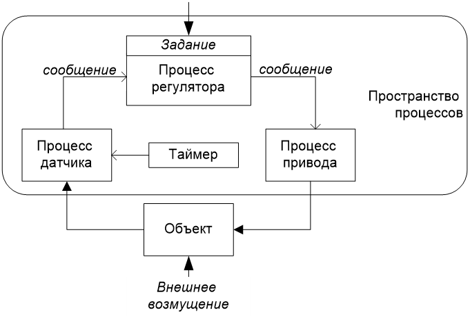
The alternative regulator circuit becomes homogeneous in its composition of elements: everything is represented by processes. The processes are parallel. Sensor data, drive parameters and exercise regulators are the states of the processes. Processes communicate by sending messages. The timer process sets the clock frequency for transmitting data from the sensor and starting a new control cycle.
Interim conclusions
The EDA architecture solution returns the sensor to active device status. Thus, when programming data processing in a stream, the control circuit becomes similar in concept to the initial classical type of analog circuit, which can cause approval from ACS specialists.
In the in-stream processing paradigm, sensors work directly without intermediaries. This speeds up the speed of signal processing.
The question may arise as to how and in what capacity a body of data exists. As the source says [1],“In the streaming model there is no shared database. The stream of events is the database.” I usually figuratively compare the flow of events with virtual wires in physical equipment: here, too, there is a race of parameters and mechanisms for synchronizing signals/events are required.
When programming an automated control system using in-stream data processing technology, two factors must be taken into account:
1) for the message sending mechanism, the processing time of the event queue is not predictable, but, nevertheless, it is sufficient for processing “lazy” technological processes with a soft response in the ms-sec range [3].
2) in communications when transmitting data, competition for the bus is possible unintentionale losses.
In contrast, implementing a control scheme in a traditional style has a significant advantage, namely predictable response time to an event. Event processing can be implemented through an interrupt, then the processing time becomes deterministic, which is very important for processing hard real-time events.
3 CAN bus
I think that many, especially motorists, have heard about the CAN standard. Standard CAN (Controller Area Network) created by Robert Bosch GmbH in the middle 1980s years. It is very suitable for processing data in a stream. Yes, yes, in the 80s there was no EDA concept yet, but there was a CAN standard!
This message-based protocol was originally developed for multiplexing electrical wiring in cars to save copper, but it can also be used in many other contexts. Now the CAN standard has begun to be used in industrial automation tasks.
According to Wikipedia, CAN is an industrial network standard, focused primarily on combining various actuators and sensors into a single network. Transmission mode: serial, broadcast, packet.
Directly standard Bosch CAN is not tied to a physical layer – it can be anything, for example, a radio channel or fiber optic. But in practice, a CAN network usually means a topology network “tire” With physical level as differential pair wires Therefore, they usually talk about the CAN bus standard.
Benefits standardand CAN buses are:
· Ability to work in hard mode real time.
· Ease of implementation and minimal cost of use.
· High resistance to interference.
· Arbitration of network access without loss of bandwidth.
· Reliable control of transmission and reception errors; the probability of not detecting a transmission error is estimated as 4.7×10⁻¹¹.
· Wide range of operating speeds.
· Availability of a wide range of products from various suppliers.
What is important is the high speed of the CAN bus up to 1Mb/s (at a distance of 40 m). For example, in the industry standard Modbus RTU the supported speed does not exceed 115 Kb/s.
3.1 Why the CAN bus directly belongs to the field of data processing in the stream
I have never seen any assessment that the CAN bus directly belongs to EDA technology. I'll try to show this.
A feature of the CAN standard that you first notice when familiarizationAnd with it attention is the lack of address space as such. Compared to the Modbus standard common in the industry, CAN has neither slaves (slave devices) nor a master (master device), there are only receiving and transmitting nodes (devices) with different data transmission priorities.
The CAN bus is a synchronous bus with the Collision Resolving access type, which provides deterministic access to message transmission, in contrast to Collision Detect in networks Ethernet. Transfer in progress personnelor in packets, and the frames are received by all devices, including transmitting devices.
Nodes begin transmitting data packets on the bus at the same time. The transmitting node simultaneously checks the bus status and continues transmission until it receives a dominant bit in the packet identifier while sending its own recessive bit. This is how the issue of conflict resolution is resolved.
The packages contain an identifier. Packets are taken from the bus to control nodes according to a unique identifier. Control nodes analyze and use the data in the packet for its intended purpose and can generate the transmission of the next packet, i.e. messages, etc.
From the above description, we can make an unambiguous conclusion that the CAN bus is fully compliant with the technology for processing data in a stream.
3.2 Scheme of implementation of systems based on CAN bus
Work with the CAN bus is organized as follows. CAN bus packets contain unique identifiers associated with the purpose. Therefore, for programmatic work in the CAN bus system, you need to know the fixed 11-bit identifier numbers. To recognize identifiers, there are CAN bus scanners.
For example, consider the hypothetical scheme presented in Fig. 4, consisting of STM-32 type microprocessors interacting via a CAN bus.
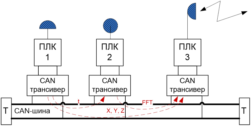
Two microprocessors (PLC1 and PLC2), equipped with sensors, receive information and transmit data via the CAN bus to the right microprocessor (PLC3), which is equipped with actuators or, in this case, acts as a communication device and transmits the data further to the analytical decision-making center. The devices are connected via CAN transceivers under general conditions and processes are running on them that “listen” to all packets on the bus. The driver library for connecting to the CAN bus can be found on GitHub.
The diagram shown in Fig. 4 is commonly used in vehicle remote monitoring, but is versatile enough to be applied to other applications. The main thing to note when looking at the diagram is:
· parallel/distributed operation of the circuit’s computing nodes,
· independence of software on nodes from each other, which can have a positive effect on the integration of software from different developers into a single system,
· although it is not obvious, the use of a proven and reliable CAN bus leads to increased speed and reliability of the system.
Result
The next article will describe the device of an audio data receiver with the considered CAN bus based on in-stream data processing technology.
Literature
1. Ben Stopford, Designing Event-Driven Systems. Concept and design patterns for stream data processing services using Apache Kafka, Irkutsk: ITSumma Press, 2019
2. E.J. Pseltis, Stream data processing. Real-time conveyor.— M.: DMK Press, 2018.
3. F. Hueschi, V. Calavri, Stream data processing. – M.: DMK Press, 2021.
4. https://habr.com/ru/companies/otus/articles/740578/
5. Yurich S., Elixir in action. – M.: DMK Press, 2020.
6. F. Cesarini, S. Thompson, Programming in Erlang. – M.: DMK Press, 2012.


