We are going solar powered. We turn the step-up DC-DC converter into a solar controller. Part 2
1. Introduction
Hello again, dear readers!
The first part of the article concerned general information on the main aspects of solar travel, the second one will be more highly specialized, designed for specialists with some experience in the field of electronics.
2. “And what, in fact, is the problem? We buy a ready-made solar MPPT controller, connect it and charge it”
As of June 2022, I only know of one model of BOOSTER solar controller: MPT-7210A. In Russian-language YouTube, laudatory video releases are known that talk about its merits.
This controller was once purchased by me:
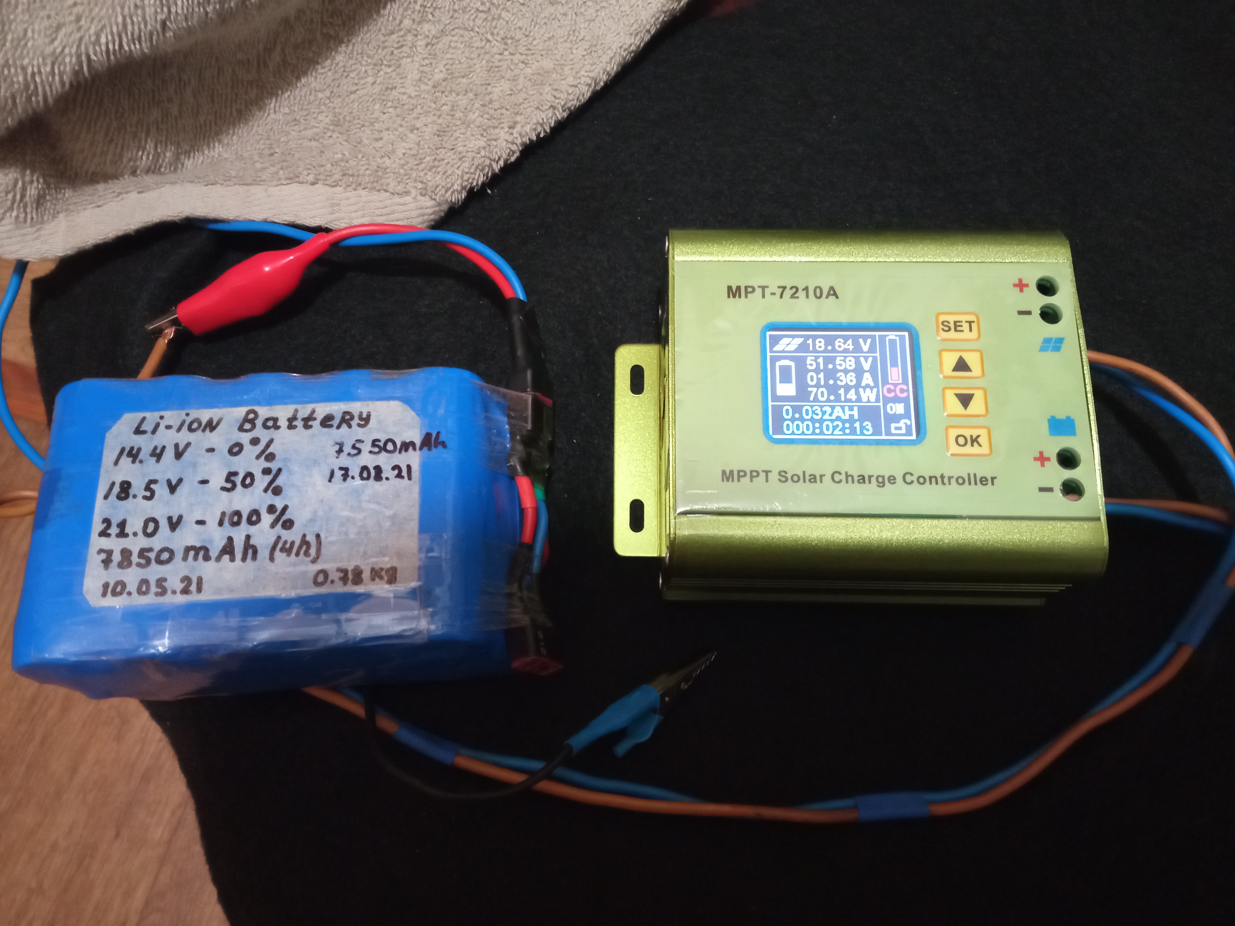
In the course of working with him, it was revealed that he is rather “raw” in terms of engineering forethought:
– firstly, it has an undocumented input current limit of about 4A (which makes it possible to pass only 70W at 18V input voltage).
By disassembling and changing the resistance of one of the shunts on the board, we managed to raise the limit to 7-8A, but it still means that the controller cannot work with panels with more than 140W of rated voltage 18V;

– secondly, the controller is declared as “MPPT”, that is, it tracks the maximum power point of solar panels. In practice, the implementation of the algorithm seemed strange to me: after manually specifying the voltage at which the search should start, the controller began to “fumble” over the entire voltage range, going to “those places” where the solar panels produce clearly little power. How to make the controller narrow the search field – I still do not understand. And without this – part of the time MPT-7210A worked with reduced panel efficiency;
– thirdly, it is not clear why the developers of the controller programmed the mode of a very slow output of the converter to full power. Relatively speaking, we have a bright Sun, the panels are ready to give out 140W, we connect the MPT-7210A and it “starts in an hour with a teaspoon”. First 10W, then he thinks, then 20W, etc.;
– fourthly, the fan hums like a Soviet vacuum cleaner. Despite the presence in the settings for adjusting its rotational speed, there is no chance to calm it down one iota. Moreover, the fan increases speed regardless of the output load. That is, at 1W and at 100W – it “vacuums” the same way.
On the plus side, I can note its excellent design, ergonomic placement of controls, a beautiful display with a lot of displayed data, but I had other priorities.
3. Priorities for the hiking solar controller
It should be:
a). Lightweight, compact and reliable.
b). Cheap, made from readily available spare parts (in conditional Arzamas, any radio component should be sold in order to repair it).
in). Without any “smart brains” that are “smarter than you”. MPRT is a nice option, but you can safely do without it if you have had solar panels for more than a month and you know in what conditions where they have the maximum power voltage. For example: in my set of panels in cold weather, the maximum power point is at a voltage of 19.0-20.0V, in hot weather – 17.6…18.2V. There is no difficulty in setting it manually and adjusting it 1-2 times a day.
G). Have high efficiency.
Market analysis revealed the absence of a model that meets these requirements.
So I had to improvise.
4. The first way to solve the problem: STEP-UP DC-DC and buffer battery 18V
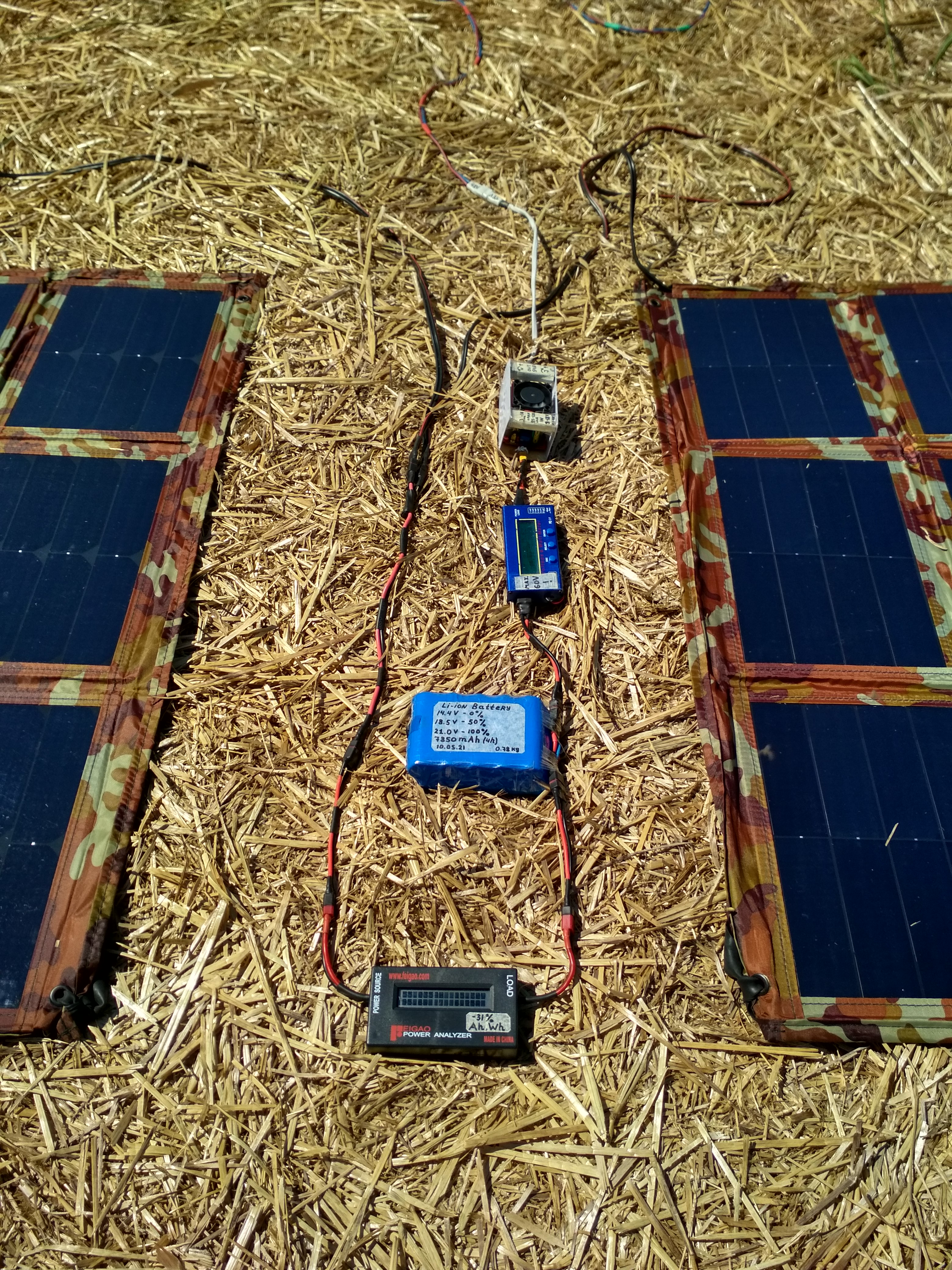
Here, the popular Chinese step-up DC-DC converter “400W” is used as a voltage booster together with a buffer Li-ion battery 18V 7.8Ah 5S2P 21700 (own assembly):
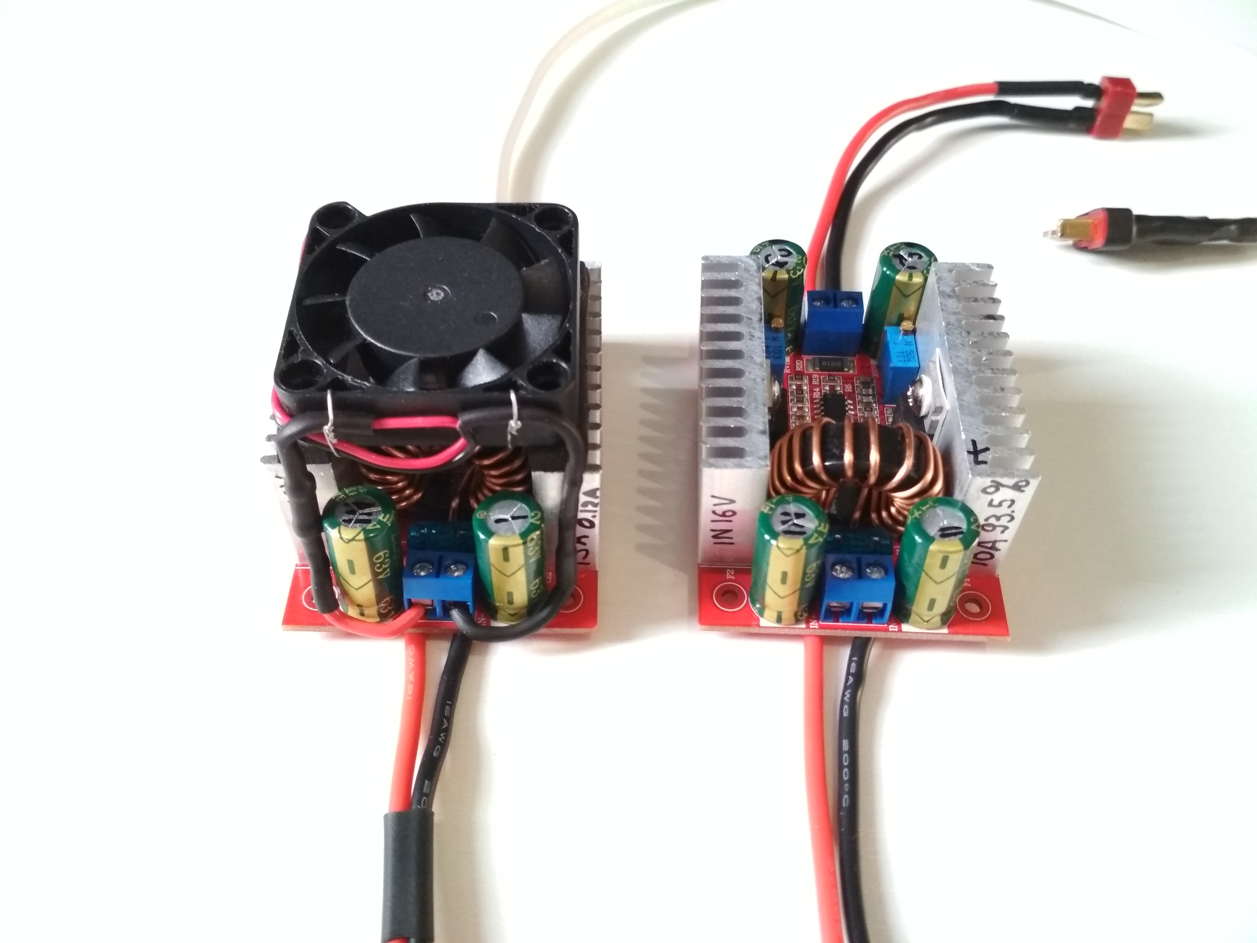
In the course of experiments, it was found that at powers of more than 100W it is desirable to equip it with forced cooling, which is easily implemented by installing a 40×40 or 50×50 cooler directly on top of the radiators.
Store link:
https://www.aliexpress.com/w/wholesale-400w-dc-dc-step-up-boost-converter.html
It turned out that the converter is quite “foolproof”: there is short-circuit protection (fuse), when overheated, only the Mosfet power switch burns out (without catching other SMD components), the power switch can be replaced with any model that meets the following characteristics:
– drain-source voltage: more than 75V;
– max. drain current: more than 50A;
– max. open channel resistance: 23 mΩ;
– max. input capacitance: 5000 pF.
Also, it has a good stabilization of the output current and voltage. It also withstood the field conditions with fluctuations in temperature and humidity, which led to the desire to keep it in the future.
With a buffer battery, I traveled for more than a year.
I have to say right now:
The obvious and simple solution to connect the usual Chinese “booster” directly to the output of the solar panels runs into the following difficulty:
The fact is that the existing adjustments on the DC-DC converter (two trimming resistors CC and CV) set the stabilization of the OUTPUT current and voltage.
Unstable current generation from solar panels and a strong steepness of their current-voltage characteristics lead to the fact that it becomes impossible to set up a drain DC-DC converter so that it takes all the power of the solar panels and does not turn off at the slightest drop in illumination.
Let’s assume that the trimmers set the output parameters: CV = 50V, CC = 2A. This corresponds to 100W of power going into the battery of an e-bike. Given the efficiency of 92% DC-DC, at least 108W from solar panels should come to the input.
Now consider the situation:
1. Bright sun. Potentially panels can give out 180W. DC-DC is working. But how? Converting only 108W out of 180. The remaining 72W is simply not used. Why? Because “native” trimmers stabilize the value of the OUTPUT power. 100W is set – it means that DC-DC will take 108W from the source and not a watt more.
2. Good. We have set the parameters so that the DC-DC generates 165W, drawing all 180W from the panels. Everything seems to be great.
3. Until a small cloud approaches. Panel generation drops three times and becomes 60W instead of 180W. But the converter is still trying to produce 165W. Where will he get them from? Nowhere. Therefore, the voltage at the DC-DC input drops below the operating threshold and normal PWM generation for the Mosfet power switch stops. Instead of 60W x 92% = 55W, we get ZERO, as well as the risk of an early failure of the Mosfet that “hangs” in a half-open state and converts these 60W into heat.
To solve this problem, it is essential to stabilize the parameters not at the DC-DC output, but at its INPUT. Moreover, it is important to stabilize the input voltage, since under different illumination, the panels greatly change the generated current, and the voltage changes very slightly.

The battery served as a buffer, storing excess charge when the current coming from the panels exceeded the current consumed by the converter, and giving off current when the Sun went behind a cloud, and the output by the panels temporarily dropped by 4-6 times. If there was no prolonged cloudiness, then the buffer battery worked perfectly for small power fluctuations, holding the operating voltage of 18-19V.
During operation, the following advantages of this scheme were revealed:
1. Incredible simplicity and the ability to work with any, the most “stupid” DC-DC converter from 18V to 48V.
2. An increase in the total energy reserve “on board” by the value of the capacity of the buffer battery.
3. Ability to briefly drive away from the camp (for example, to the nearest village for water) leaving all equipment in place, while watt-hours continue to accumulate.
4. You can move solar panels with a small battery without dragging an electric bike in search of a place with the best illumination (at first, when the topic of solar panels was at the initial stage of study, this was very important from a scientific and experimental point of view).
And disadvantages:
1. Increase in the weight of the equipment carried by 0.8 kg
2. There was an inability to “guess” the exact position of the booster power so that the charge flowing into the buffer battery was exactly equal to the charge flowing out of it. Because of this, the voltage “floated”: either up or down, which did not allow for a long time (more than 1-2 hours) to move away from the charger. It was necessary once in a certain period of time to approach, look and twist.
5. Scheme for protecting the buffer battery 18V from discharge
The study of opportunities to automate the process of monitoring the state of charge of an 18V buffer battery began relatively recently, when the main passion for riding on solar energy was satisfied and there was a desire to upgrade equipment.
It was necessary to introduce an additional feedback loop into the boost DC-DC converter circuit.
Stock variant scheme:
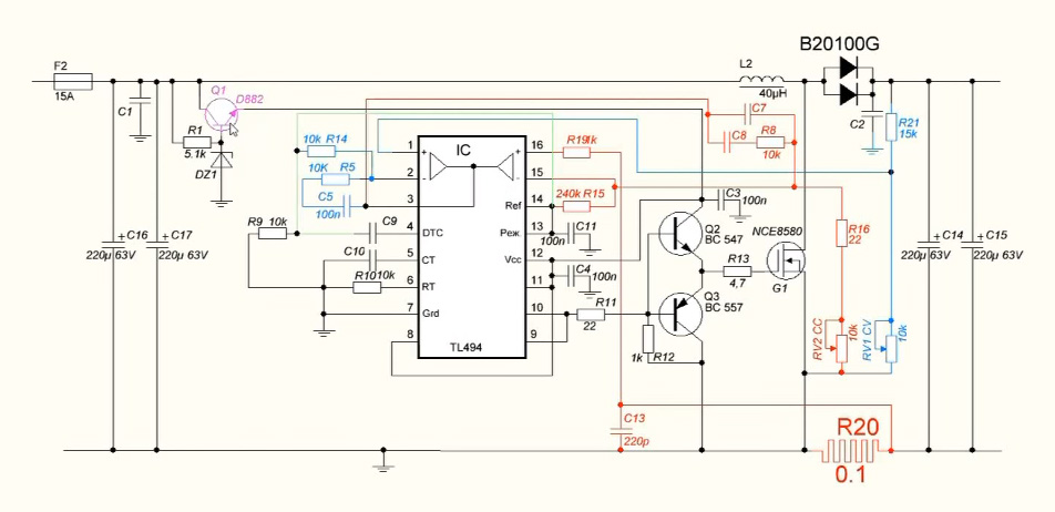
In the process of experiments with the converter, it was found that applying an additional positive voltage to pin 16 of the TL494 PWM generator chip leads to a decrease in the conversion power.
It should be said that the inputs 1, 2, 15, 16 of the microcircuit are analog and the control goes with voltages of a few to tens of millivolts.
To implement the input voltage control circuit, an additional board was assembled based on a controlled zener diode-microcircuit TL431:
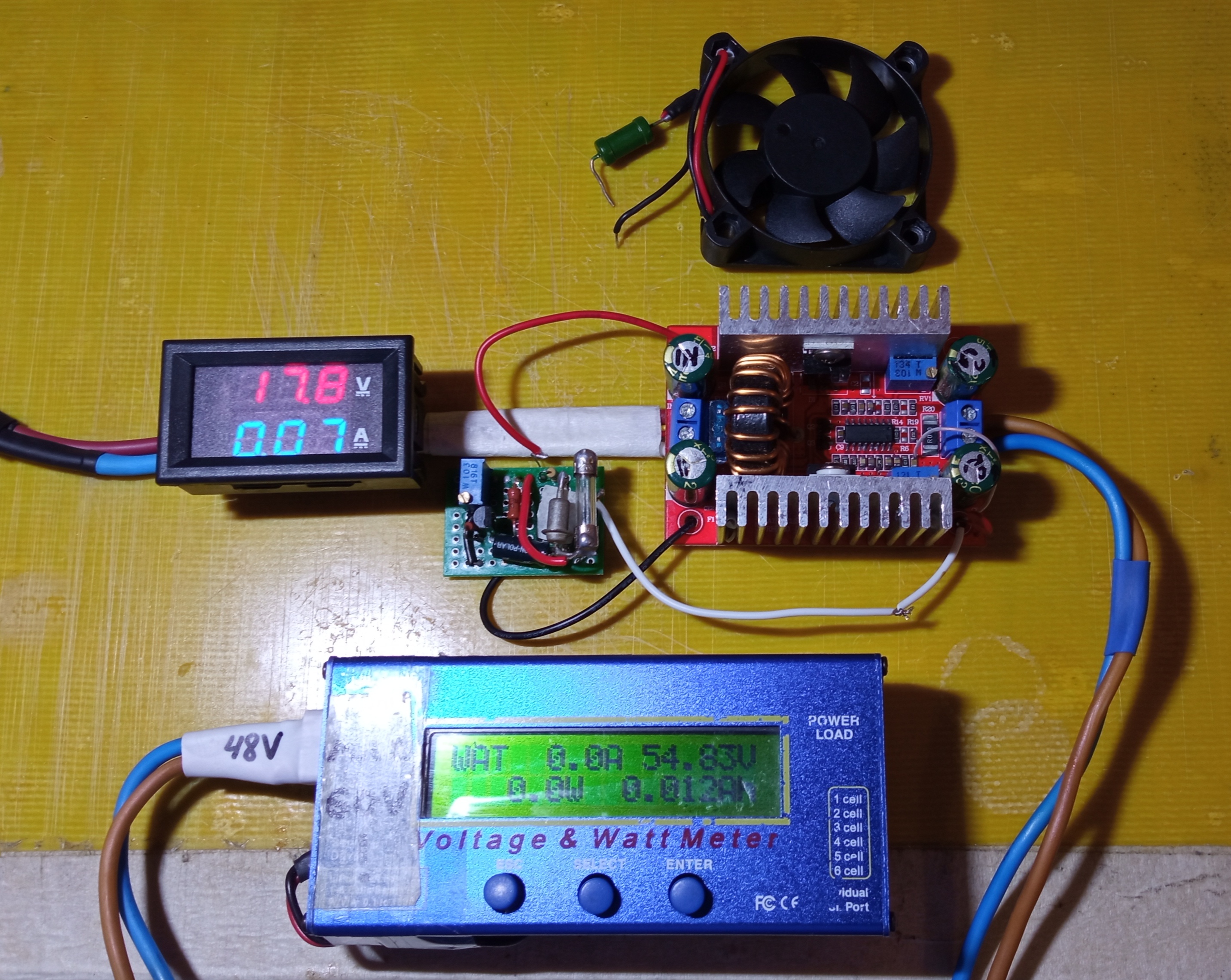
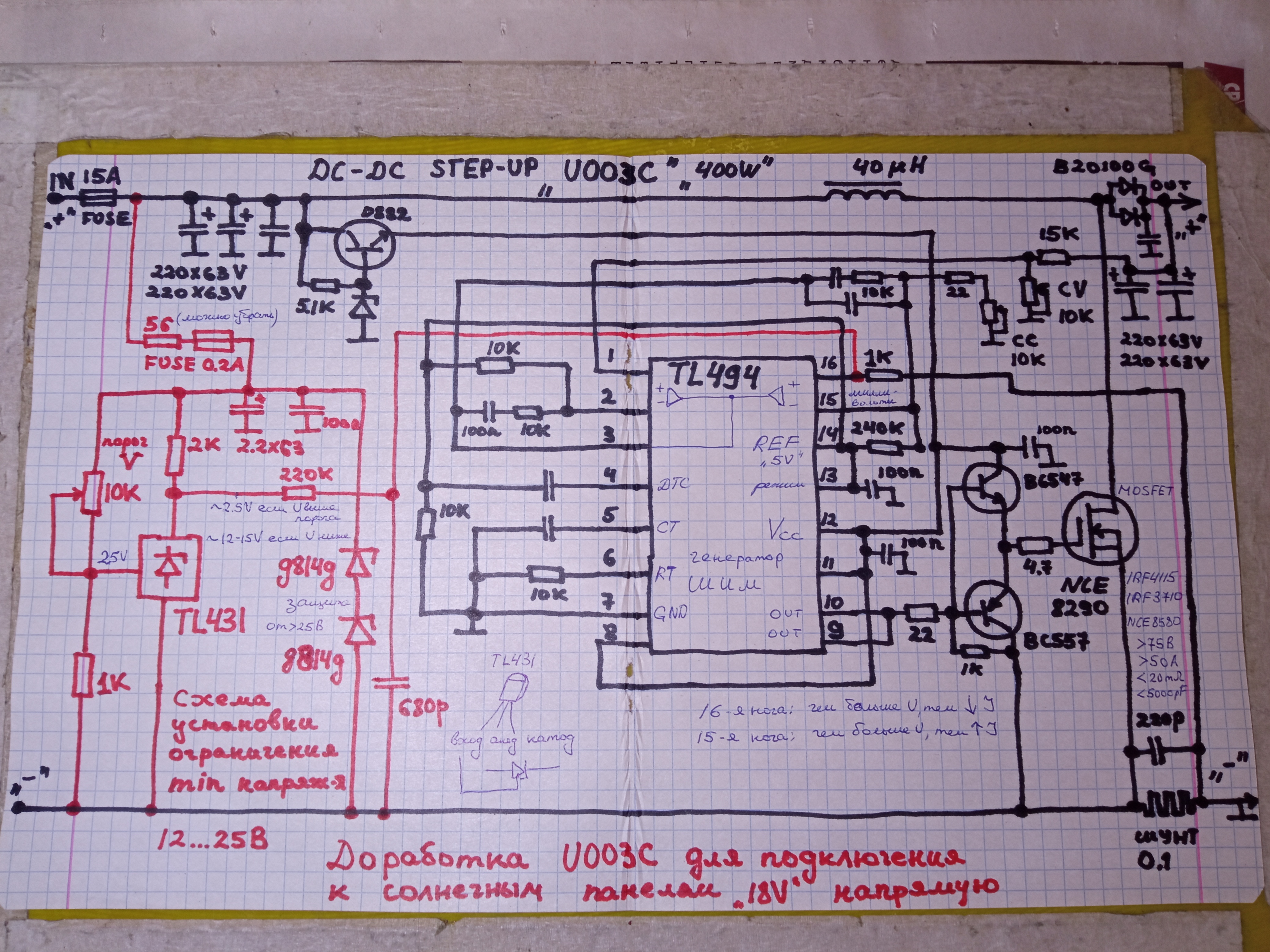
The circuit’s job is to monitor the input supply voltage. At the moment when the supply voltage drops below the threshold set by the divider, the TL431 microcircuit stops passing current through itself, and an increased voltage level (12-15V) begins to come to the input of the TL494 microcircuit (pin 16), through a 220kΩ terminating resistor, from the TL431 cathode. A high signal level causes the TL494 to reduce the current converted by the DC-DC converter to zero.
As the supply voltage at the input increases, the TL431 opens, “lowers” the voltage across the 2kΩ resistor to the level of 1.8V (the minimum voltage for the TL431 to work), the signal level at pin 16 of the TL494 chip decreases sharply, and, as a result, the battery charging current increases electric bike to the value set by the standard trimmer for adjusting the output current on the board of the converter itself. The additional block practically ceases to influence the operation of the DC-DC converter. The transient process occurs in the input voltage range of 0.2-0.3V.
A 0.2A fuse and two D814D zener diodes connected in series serve as a circuit to protect the additional board from increased input voltage. The fact is that the TL431 chip has a limit of 36V, while the DC-DC converter supports input voltage up to 50V. If a voltage of more than 25V comes to the input, then the zener diodes will open, a large current will flow and the fuse will burn out, disconnecting the additional board from the power supply. Here you can put any other powerful zener diode with an operating voltage of 25 … 34V (should be more than the open circuit voltage of the connected solar panels).
It is impossible to put a resistor with a resistance of more than 56 ohms in series with the fuse, since during the tests it was found that this violates the clarity of switching the TL431 chip when the set threshold is reached. This resistor can be excluded from the circuit altogether.
6. Bonus
During the experiments, the circuit showed stable operation and its additional property unexpectedly emerged: it became possible to completely abandon the 18V buffer battery and connect the solar panels directly to the converter. The operating voltage was set at the level of the threshold set by the trimmer on the additional board. At the same time, the current generated by the solar panels at this voltage became exactly equal to the current consumed by the converter.
Tests of a boost converter with an input voltage stabilization circuit are demonstrated in the following video:
https://www.youtube.com/watch?v=CoyKqMDN4so&t=191s
At operating currents of 4-8A, the circuit also showed its performance (later additional tests were carried out that were not included in the video).
7. Conclusion
In the course of refinement, a full-fledged solar controller was obtained with manual setting of the operating voltage of solar panels with the following parameters:
– input voltage range: 12…25V
– input current range: 1…10A
– output voltage: 20…63V
– conversion power: 1…250W
– weight: 0.2 kg
– measured efficiency 91…93%
That’s all for me, dear readers. Ahead I have to test this refinement in long trips, the results of which you will know.
Of course, there is a possibility that bugs and other unpredictable nuances may surface during operation, so the scheme for repetition is recommended by those who are potentially willing to experiment.
Thank you all for your attention!