USB Type-C hardware implementation options, or When Power Delivery is not required

When we at SberDevices make a new device, work on its hardware, we are faced with the question of choosing interfaces. An important point when choosing is their availability and compatibility with other devices.
In our devices, we could not pass by the USB-C interface. In addition to being very popular in modern devices, it has significantly expanded the functionality of USB over its predecessors. Let’s talk about it in more detail.
A Brief Overview of USB TYPE-C Features
USB standards have been around for many years, evolving and improving as technology needs and capabilities increase. Despite its versatility, which follows from the abbreviation, the usual USB has ceased to satisfy in terms of its functionality. In particular, it cannot solve the problem of providing power to many modern devices, the consumption of which has seriously increased. The first version of USB TYPE-C appeared in 2013. In addition to the capabilities of USB 2.0 and USB 3.0, USB-C now supports significantly more power-intensive power profiles, as well as alternative operating modes. In alternative modes, the pins of the connector are used to transfer data of high-speed standards such as Display Port, Thunderbolt, HDMI, Mobile High-Definition Link (MHL). Recently a new implementation of the standard, USB4, was published, which also focuses on the USB-C specification.
Description and purpose of connector contacts
The connector includes 24 pins. Such a large number of contacts in comparison with the usual USB connectors is associated both with the addition of new contacts, expanding the functionality, and with duplication of contacts on the opposite part of the connector. So the groups of signals USB 2.0 and USB 3.0 are duplicated, the connector has become symmetrical, so now it can be inserted either side.
Consider the signal groups of the USB-C connector:
| Group | Chains |
|---|---|
| Nutrition | VBUS (4 pins), GND (4 pins) |
| USB 2.0 | DP (2 contacts), DN (2 contacts) |
| USB 3.0 | TX1 +, TX1-, TX2 + TX2-, RX1 +, RX1-, RX2 +, RX2- |
| Configuration contacts | CC1, CC2 |
| Advanced (Alternate Mode) | SBU1, SBU2 |
It can be seen that 4 pairs of contacts are laid for power. This hints that it became possible to deliver significantly more energy through the connector to power the device. The power contacts can transfer up to 100 watts to the load.
Power profiles available via USB TYPE-C:
| USB 2.0 | 5 V 500 mA |
| USB 3.0 / USB 3.1 | 5 V 900 mA |
| USB BC 1.2 | 5 V, up to 1.5 A |
| USB Type-C Current 1.5A | 5V 1.5A |
| USB Type-C Current 3.0A | 5V 3.0A |
| USB Power Delivery | up to 20 V, up to 5A |
The power mode depends on what USB-C functionality is being used. The new CC contacts allow you to set the required power mode and open some additional possibilities, but more on that later.
To be able to use the high current power profile, use the CC configuration pins when making the connection.
CC configuration contacts
Using the CC (Configuration channel) configuration contacts, two devices are connected, the connection parameters, power profiles are set, as well as information exchange of the USB Power Delivery protocol. Functionally, CC1- and CC2-pins solve the following tasks:
- Determination of cable orientation.
The connector has two configuration pins, but only one of them is connected via a cable to the CC-pin on the opposite side. By which of the two pins is connected, you can understand the orientation of the cable. The second can be reassigned as a VCONN pin to supply active cables.
- Determining the roles of connected devices.
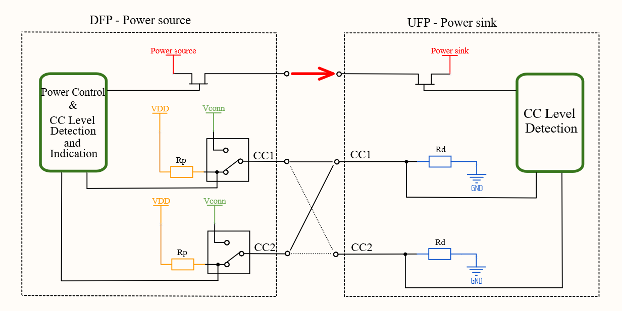
When establishing a connection, it is necessary to determine who will act as a power source (Power Source) and a consumer (Power Sink). From a communication point of view, you need to define a Downstream Facing Port (DFP) host and an Upstream Facing Port (UFP) device.

The source (aka DFP) pulls the CC lines to positive through resistors Rp or uses current sources. The consumer (UFP), in turn, pulls the CC lines to minus through the resistors Rd.
By setting a certain Rp value (or creating a certain current on the CC line), the host tells how much current it can provide to power the device. By measuring the voltage drop across Rd, the consumer understands which Rp is being used at the opposite end and therefore determines the supply current that the host can supply. Without using USB Power Delivery, using this scheme, it is possible to establish a connection with a current of up to 3A with the only possible voltage of 5V.
- A channel for exchanging messages using the USB Power Delivery protocol.
I will discuss this in detail in a separate article.
Cost-effective implementation without USB PD
Description
As seen above, the USB-C specification supports a wide range of data transfer standards and power profiles, but this does not mean that the developer is obliged to use all the functionality. The minimum set of USB TYPE-C can include USB 2.0 with CC pins and a single supply voltage of 5V. In this configuration, it is possible to provide the consumer with up to 15 W (5 V, 3A), which is much more than the standard USB 3.0 port – 4.5 W (5V, 900 mA) can give.
Implementation
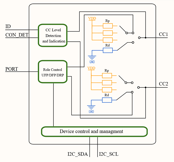
To implement the connection logic between DFP and UFP, you can use a CC configuration controller chip such as PTN5150. This option is much simpler and cheaper than fancy controllers that support USB Power Delivery. The block diagram looks like this:

As you can see, the main nodes are: a voltage monitor on the SS contacts, a set of current sources, resistors for switching the state of outputs, a module for controlling the roles of the device.
The microcircuit has an I2C interface, with its help you can define or change the role of the device (DFP, UFP, DRP).
When the DFP role is selected, the device is assumed as a Power Source, for which there are 3 power profiles to choose from. After setting the appropriate bits in the control register, the corresponding current source is connected to the CC line.
| CC line current | Diet |
|---|---|
| 80 uA | 5V / 0.9 A |
| 180 uA | 5V / 1.5 A |
| 330 uA | 5V / 3 A |
If the microcircuit is defined as a UFP, the CC pins are connected through a 5.1 kΩ resistor to ground. The monitor measures the voltage drop across this resistor and the current power mode is entered into the status register.
It is also possible to set the role of Dual Role Power (DRP), in this mode the microcircuit sequentially changes the state of the CC contacts from “pull-up Rp” to “pull-down Rd” and back until the connection is established. Connection is only possible between one source (Power Source) and one consumer (Power Sink). Thus, when the microcircuit is in DRP mode and the voltage monitor of the CC pins notices a decrease in voltage at the opposite end (“pull-down Rd” is connected), the device realizes that it is connected to Sink and begins to play the role of Source. This mode is useful in the case when it is not known in advance in which mode the device should operate.
Let’s consider an example of using a controller
In addition to the CC pins and the I2C bus described above, it is worth noting the ID, CON_DET, PORT pins separately. The ID pin displays the mode the controller is currently in. When the device has identified itself as a DFP, the ID will be set to LOW. The CON_DET pin is HIGH when the connection is established, LOW otherwise. We will use these two logical signals further to turn on (when we are DFP) and turn off (UFP) the power of the connected device.
Port is an input that sets the initial device mode after power-up. In the case where pull-up is used, the controller becomes DFP, if pull-down is UFP. If the leg is left “hanging in the air”, Dual Role mode will be used, and the device will wait for the connection to determine its role. This state can be changed later after configuring via I2C or changing the voltage level on PORT. In this way, it is possible to control modes of operation without using I2C.
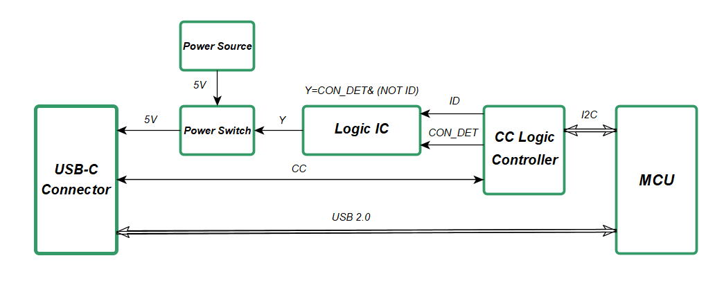
It is necessary to control the power supply of the external device, for this you can use an additional logic chip and a key.

Our task is to supply power to the USB-C connector only when UFP is connected to us. ID in this case will be LOW, CON_DET will be HIGH. In order to open a key with a high level of HIGH, you need to implement the function Y = CON_DET & (NOT ID). Thus, if the UFP is connected outside, it is powered from us, if DFP, then the voltage is not supplied to the connector and there is no conflict between the two sources.
If there is no task to change the role of the device during operation, and it is also not required to determine the orientation of the cable, it is possible to perform the option more simply, without a microcircuit at all. Let’s say your device plays strictly one role – UFP / Power Sink, for example, it’s a flash drive. In this case, it is enough to connect the CC1 and CC2 pins on the connector through 5.1 kOhm to ground.
If your device only plays the role of a DFP / Power source and it must be connected to a USB-C Dual Role device, you can also do with resistors. In this case, we select the ratings depending on the voltage of the source to which we connect the resistors.
| CC line current | Diet | Pull up to 5 V, kOhm | Pull up to 3.3 V, kOhm |
|---|---|---|---|
| 80 uA | 5V / 0.9 A | 56 ± 20% | 36 ± 20% |
| 180 uA | 5V / 1.5 A | 22 ± 5% | 12 ± 5% |
| 330 uA | 5V / 3 A | 10 ± 5% | 4.7 ± 5% |
We looked at relatively simple and cheap ways to make our device compatible with other USB-C devices when we want to use only a subset of the spec’s features. The capabilities of the standard are not limited to this, Power Delivery and Alternative modes significantly expand the available functions, but they increase the cost and complexity of the device. I will talk about these possibilities in the following articles.


