two cameras Raspberry Pi and Python

While an intern at a government technology agency in Singapore, the author worked on an experiment to create an alternative to the Intel Relsence camera. It turned out that there were few training materials on the topic of machine vision, so he decided to help beginners. To the start of the flagship data science course invite under cat for details.
Have you ever wondered how the Terminators actually see the world? How do they know about the approach of the enemy? The answer is in the two demonic eyes in the picture above. The terminator’s eyes are able to look in one direction, giving it binocular vision. In fact, these sci-fi robots, including their eyes, are based almost entirely on the human body.
Each eye captures separate 2D images, and the magic of depth perception actually happens in the brain, which extrapolates the similarities and differences between the two images.
Simple stenop is based on the physics of the human eye and, like the eye, loses depth information due to perspective projection. But how are we going to measure depth with cameras? We use two cameras.
Why is it important?
Before diving into the “how” question, let’s deal with the “why” question. Imagine that you need a trash robot, but don’t want to invest in heavy lidar technology to determine how far away a trash can is. This is where stereoscopic vision comes into play.
Using two conventional stenops, not only for depth determination, but also for machine learning tasks such as object detection, can save a lot of money. Moreover, this technology can achieve results similar to, if not better than, other technologies.
Even an organization like Tesla has said no to the use of lidars in their autonomous vehicles and relies on the concept of three-dimensional radar vision. Watch this video from Tesla:
Obviously, instead of 2 cameras, Tesla uses 8, as well as other sensors, such as radar.
Diving into stereo vision is a great way to get started with computer vision and imaging projects, so let’s continue to learn more about 3D vision.
Fundamentals of multiview geometry
Epipolar geometry:
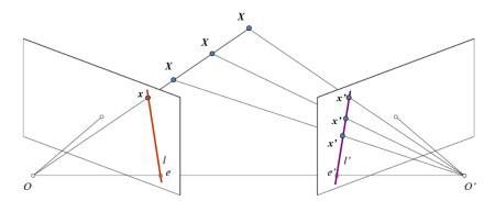
Consider two chambers with holes, O and O′. Each of them sees only a two-dimensional plane. If you focus on camera O, then x is projected to only one point on the image plane. However, the image from O′ shows how different points of X correspond to points of X′.
Under these circumstances, through left-to-right alignment, it is possible to triangulate the correct data points in 3D space – and sense depth. To learn more about polar geometry, check out this article from University of Toronto.
What will lead us to volumetric vision?
Volumetric vision can be achieved in 4 stages.
1. Correction of distortions. It involves the removal of radial and tangential distortions that occur in images due to camera lenses.
2. Rectification of two cameras is a transformation for projecting images onto a common plane.
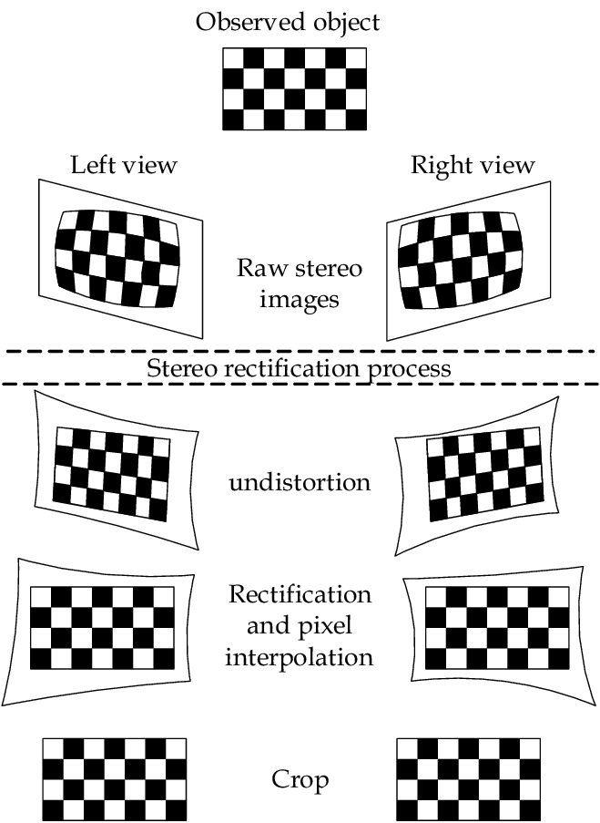
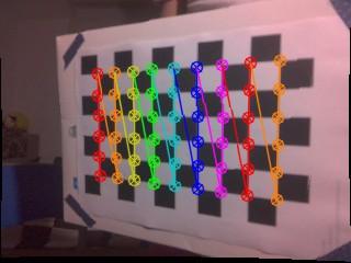
3. Point matching, where we find matching camera points by straightening the left and right images. Usually, a checkerboard image is used for straightening.
4. Create a depth map.
Is it possible to do such a project yourself?
Definitely yes. It only takes a few things to start a project.
Jetson Nano Developer Kit B01 (with two camera slots CSI).
Two Raspberry Pi cameras.
Interest!
I realized that there are not many educational materials on the topic, so I wrote a series of articles to share with newbies and enthusiasts like me, to help them speed up learning and project implementation. To start developing your own depth mapping machine, just read on.
This project is a good way for beginners to take a step not only into the field of computer vision, but also into computer science in general, gaining skills in working with Python and OpenCV.
Depth Map

Now that we understand the concept of volumetric vision, let’s start creating a depth map.
Let’s start the camera
All scripts used in this tutorial are written in Python. Clone to get started repository stereovision.
Requirements
If you don’t have a Jetson Nano, please visit this site. Assuming you already have Jetson Nano installed, install the Python 3.6 dependencies:
sudo apt-get install python3-pipPython 3.6 development package:
sudo apt-get install libpython3-devAnd dependencies:
pip3 install -r requirements.txtIf you want to install dependencies manually, run this code:
pip3 install cython # Install cython
pip3 install numpy # Install numpy
pip3 install StereoVision # Install StereoVision library
If you encounter any errors while working on a project, please refer to this section of my repository.
Testing cameras
Before creating a case or stand for a stereo camera, let’s check if the cameras are connected. You can connect two Raspberry Pi cameras and check if they start up with this command:
# sensor_id selects the camera: 0 or 1 on Jetson Nano B01
$ gst-launch-1.0 nvarguscamerasrc sensor_id=0 ! nvoverlaysink
Try it with sensor_id=0to check if both cameras are working.
If you encounter a GStreamer error like this:

then enter the command below in the terminal and try again.
sudo service nvargus-daemon restartSometimes the GStreamer pipeline does not close properly when exiting a program. Therefore, the command is very useful, it should be remembered. If the problem persists, make sure the camera is connected properly and restart the Jetson Nano.
pink shade
If you see a pink tint, please follow the instructions below to remove it. recommendations from this article.
Iron preparation
Before proceeding, you should have a stable stereo camera with two Raspberry Pi lenses spaced at a fixed distance from each other – this is the baseline. It is important that she always remains still.
My optimal baseline is 5cm, but feel free to try different separation distances and comment on the results. There are many ways to do this, use your imagination!
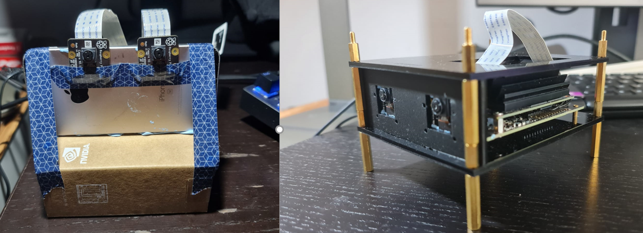
I first used BluTac to glue the cameras to an old iPhone and a Jetson Nano box. So I decided to use onShape to design a simple 3D model in CAD, cut out the pieces from acrylic with a laser cutter, and I got the enclosure like the aviary you see on the right.
If you are interested, you can look my design. And if you want to develop your own model, you can download the 3D STEP model base here.
Launching the cameras
After making sure that the cameras are connected correctly, let’s start them. In terminal go to directory /StereoVision/main_scripts/, run the python3 start_cameras.py command. You should see a live feed from two cameras on the left and right. If you encounter errors while launching the camera, visit this page.
Preparing the chessboard
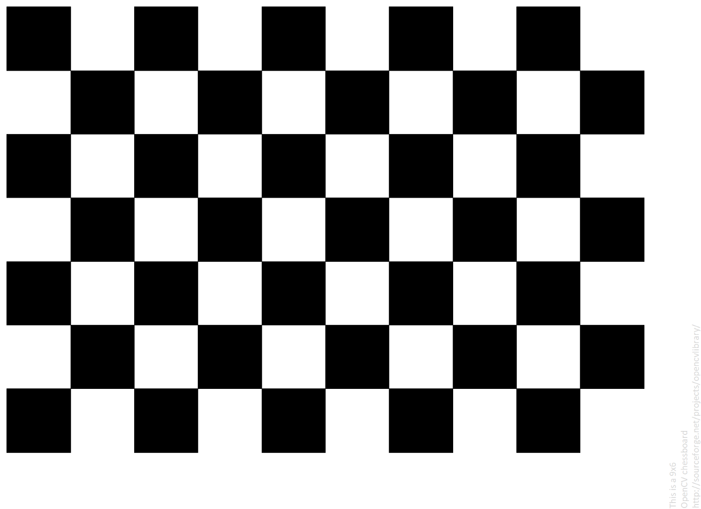
Print the image. Make sure it doesn’t fit the page or change scale, and stick it on a hard surface. The easiest way is to use an image of a checkerboard. But, if you want to use your board, change the 3_calibration.py script on lines 16 and 19. We will get 30 images at intervals of 5 seconds.
Here’s what else I suggest
don’t stand too far. Make sure the board takes up most of the camera frame;
all corners of the frame are covered;
be sure to move and rotate the board between shots to get photos from different angles.
Slowly move the board between images and be careful not to cut off part: the images from both cameras will be stitched together and saved as one file. To take pictures run this code:
python3 1_taking_pictures.pyIf you encounter an error when starting the cameras Failed to load module "canberra-gtk-module"try this command:
sudo apt-get install libcanberra-gtk-moduleIf you want to increase the time span or the total number of pictures, modify the 1_taking_pictures.py script. You will find the photography settings at the very top of the file. Change it:
#These are the first few lines from 1_take_pictures.py
import cv2
import numpy as np
from start_cameras import Start_Cameras
from datetime import datetime
import time
import os
from os import path

#Photo Taking presets
total_photos = 30  # Number of images to take
countdown = 5  # Interval for count-down timer, seconds
font = cv2.FONT_HERSHEY_SIMPLEX  # Cowntdown timer font
And if you want to stop any program in this series of articles, press the Q key. You will get the images folder with all the saved images.
Working with images
To ensure that the calibration images are of good quality, we will review each photo taken and accept or reject it. To do this, run the python3 2_image_selection.py command.
Run through all the images: Y – accept the image, N – reject it. Images from the left and right cameras will be saved separately, in the pairs folder.
Calibration
This is the most important step in the entire article series. To get a map of inequality, you need to straighten and calibrate the cameras. More about camera rectification.
Thanks to library for Daniel Lee’s stereo vision, we don’t have to work much in terms of code. To perform the calibration, let’s go through all the chessboard images saved in the previous step and calculate the correction matrices. The program will match the dots and try to find the edges of the checkerboard dot. If you feel that the results are inaccurate, try taking repeated shots.
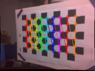
To calibrate, run the command python3 calibration.py.
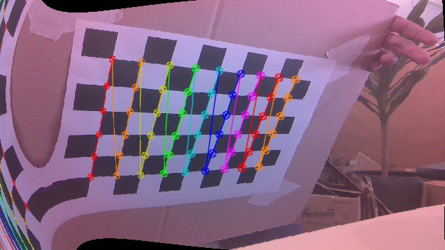
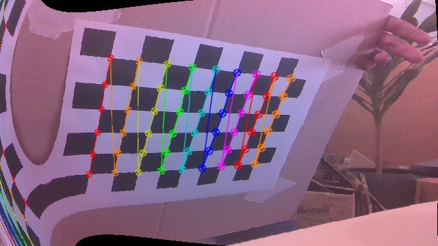
If the calibration results look a little strange, as shown above, you can try repeating steps 1-3. Your rectification images will never look perfect, so don’t be afraid of the results and move on to the next step. You can always return.
Setting the depth map
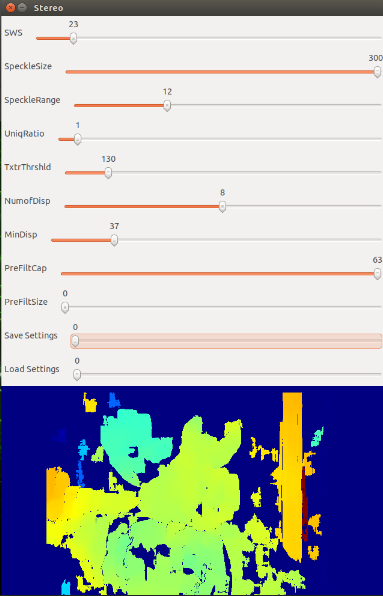
Now that the camera is ready to go, let’s start setting up the depth map. Execute the 4_tuning_depthmap.py script. To understand the variables of this script, see the README in the repository.
The setting ranges may differ slightly from those indicated in the explanations: due to limitations in the trackbars, I had to change the options displayed in the GUI. In the adjustment window, you will see the rectified left and right grayscale images.
Depth Map
That’s all. You can run the 5_depthmap.py script: python3 5_depthmap.py. Here it is, a fully functional depth map that we created from scratch.
Distances to objects
The depth map you see above is a 2D matrix. Why not get depth information from it? To find out the distance to a specific object in the frame, click on this object and you will see the relative distance to the terminal in centimeters. It determines how far the pixel is from the camera.
What does it mean?
One thing to understand is that the measured distance is not the exact distance from the center of the camera system, but the distance from the camera system along the Z axis.

So the measured distance is actually the Y distance, not the X distance.
Other tutorials
You can continue learning machine vision and Python from the very beginning or upgrade your skills in our courses:
Choose another in-demand profession.

Brief catalog of courses and professions
Data Science and Machine Learning
Python, web development
Mobile development
Java and C#
From basics to depth
As well as
