Turning network equipment on and off with a momentary button
There was a task to develop a block that could include some devices connected to a 220V network. Devices are underpowered. It seems that there are no problems to solve the problem, just a switch? 🙂 A requirement has been added to the task: the devices must be turned on by pressing the anti-vandal button, which does not have a fixation, and by the second pressing – turn off. This makes things a little more difficult, but not much. And here’s how I solved it.
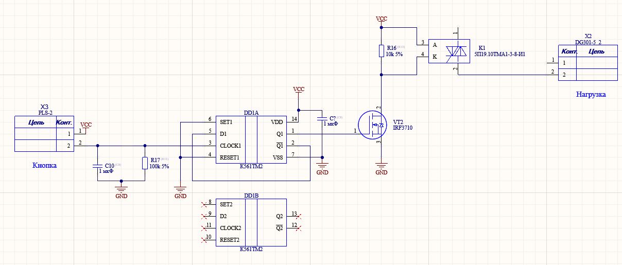
To work with a non-latching button, I chose the simplest solution on a D trigger. I have two K561TM2 boxes and you can buy a bunch of cheap foreign analogues, such as CD4013. I want to say right away that there are many options for making an electronic fixation of a button on several transistors, a diode and a capacitance. And yes, these solutions will also work quite well. I just wanted to do as described below.
I don’t want to use just electromechanical relays to switch different loads, since there is no complete understanding of what can be connected there, what type of load. Even a low-consuming load that has some peculiarities with cos φ can weld the relay contacts. This is the power factor. Loads are not always ideal. Very rarely do we switch just a resistor or a heater. Increasingly, devices connected to the network have reactive components in their load characteristics. And this means that there is a displacement of current from voltage in phase. To do this, the load must have a capacitive or inductive component, noticeable for the mains frequency, in order to shift the phase of the current from the voltage. Many relays indicate the switched current at the switched voltage and the same cos φ, but you never know what they can connect. That is why it seemed to me a more reliable solution in the prototype to use a solid-state relay on a thyristor – why not? Power allows.
It remains to somehow power the electronic button lock. Here is the most interesting. I looked at the button that will need to be pressed and did not find any descriptions and parameters. The usual anti-vandal button made in China. Although initially it was not said about the galvanic isolation of the button, I think it would be simply not human not to do it. Therefore, the decision to use a capacitive divider and stabilization on a zener diode is similar and some kind of viper was not even considered. There is something left with the transformer.
Thus, the block diagram turned out:
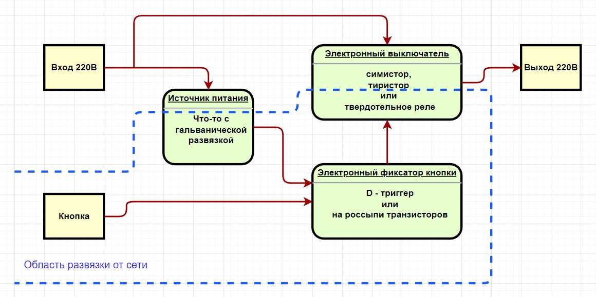
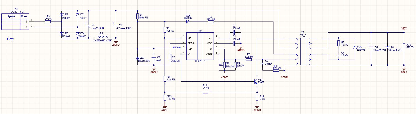
Nutrition. The main thing is not to make a custom transformer (or choke, because the flyback turned out in the end). And here many companies that produce ready-made small-sized pulse transformers come to the rescue. And what’s important you can easily buy them. The choice fell on the cheapest, but with the specified insulation voltage> 3 kV. It turned out pretty interesting. I didn’t select a transformer for the circuit, but I found a transformer for 10 rubles and read what circuit it was designed for, and applied it. The transformer was made to work with a microcircuit of a rather serious manufacturer Melexis, but at the same time quite cheap and common. The transformer + microcircuit cost 20-25 rubles at retail.
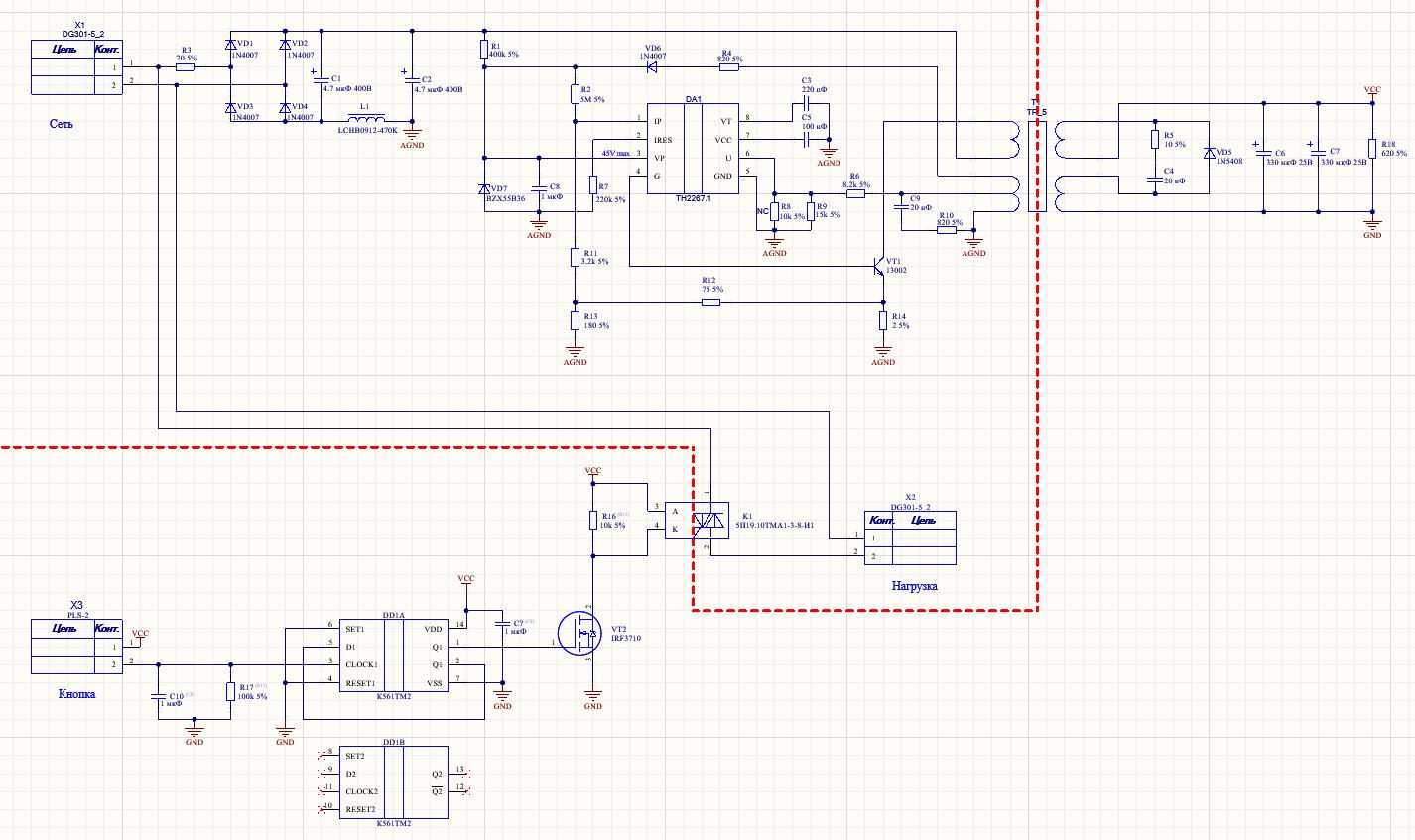
After selecting the main elements, a block diagram was drawn. Since this was a prototype and no special optimization was required, at this stage, for the most part, what was easier and faster to buy was applied. On the prototype, I provided the possibility of using a block with an OK output, just in case. To do this, I simply laid a more powerful transistor, which should drive a solid state relay.
relay was the one with which you have already worked is selected and was confident in its reliability.
After the circuit that performs the main functions of the block, a power supply circuit with galvanic isolation was drawn. The circuit is taken from the datasheet and the options for turning it on shown on the transformer.
Since at first it was necessary to make and test one sample, it was decided to make the board using the classic amateur radio method – laser ironing.

Since I am not a guru of the laser ironing method of making boards, the board was designed with wide traces and large gaps between them.
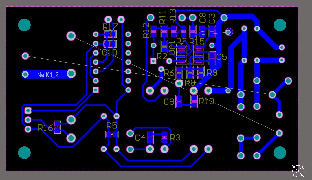
I decided not to run the power tracks to the output connector and the relay on the board, but simply make them with external wires. For tests will go.
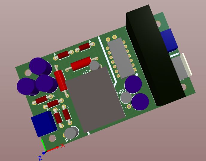
Well, this is how it looks like in 3D in CAD.

After manufacturing and assembly, the high-voltage circuits were checked for short circuits (since the board was not made at the factory, but in my bathroom, there could have been inconspicuous stains). And checking the correct polarity of the installed cells, especially high-voltage electrolytes.

On the transistor VT1, just in case, a metal bracket was put on as a temporary radiator.

Commissioning
To begin with, I energized DD1 from a laboratory power source and made sure that the relay control circuit and button fixation worked correctly. Everything is expected here, but I try to check everything for stupid mistakes.
Next, I applied voltage to 3 pins of the DA1 microcircuit from a laboratory power source and made sure that it was working and ready to control the transistor.
Next, a trial connection from a 220V network.
I always recommend switching on such structures by connecting them in series with an incandescent lamp (usually for 220V, and select the power depending on the device under test and testing options). And I recommend feeding it when you first turn it on through LATR.
Personally, for myself, I have a tricky scheme for such first launches.
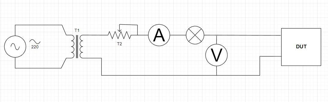
Transformer T1 1:1 network for galvanic isolation from the network. Mine has a power of about 400W and rarely has it been lacking. Further, LATR, designated as a resistor (T2), allows you to smoothly raise the voltage. The incandescent lamp will simply light up in the event of a short circuit in the device, or its faint glow will indicate unexpected consumption. The ammeter and voltmeter are just really handy for monitoring what’s going on right now.
In principle, everything went like clockwork for me, the unit worked without any problems.
I want to note that C10 set to the ground or to the power supply of the trigger sets its initial state. Since the circuit is quite simple and does not have special resets before starting, this remark may be useful.
After the initial check, there were various tests and trials, the block was slightly redesigned, more professionally made. It turned out that my idea with a galvanically isolated power source was very useful and became a standby power in the device. I don’t have the right to show the final version, but this example can be taken as a reference and used in your crafts.