Russian BIM-technologies: design of external engineering networks in Model Studio CS

Continuing to acquaint our readers with the materials of the webinar “Unified AWP based on Model Studio CS and nanoCAD”held by the specialists of CSoft Group on October 20, 2020, we present the capabilities of the automated workstation (AWP) “External Engineering Networks”.
Introduction
AWS “External Engineering Networks” is a link between the modules Model Studio CS Master Plan and Model Studio CS Piping… The software product is designed to build extended engineering networks connecting buildings and structures. Such engineering networks are a structure consisting of one or more pipes, as well as accompanying construction or auxiliary elements: a channel, a case, overpass supports, etc. Among the communications designed using these workstations are heating networks, which consist of two pipes running along the same axis, and multi-pipe racks. It is possible to work with a bundle of pipes or cables – elements that run along the same axis.
Collaboration technology with a single base Model Studio CS
AWS “External engineering networks” requires a prepared project database. The database should be deployed in CADLib The project, which allows to combine the designed object models in all specialties in a common information space, use the sub-model as a basis, link 3D models to tasks and to correspondence between project participants.
At the very beginning of the work, the designers working in the Model Studio CS Master Plan connect to the project base using the CADLib Project technology and create the site topology: design and existing surfaces, urban planning regulation zones. This allows the user of AWS “External engineering networks” to carry out design based on the terrain.

Working with a database of items
Let’s consider in order the main functionality of the AWS “External engineering networks”. And let’s start with item database, since it is it that contains all the data for the automatic construction of the utility network.
AWS “External engineering networks” allows you to work with the base of elements, products and materials, built into the design environment and does not require calling third-party programs: access to it is carried out through a convenient dialog box. The base contains pre-created elements of the section of utility networks and three-dimensional objects for generating a full-fledged model based on data from the plan and profile of the utility network. Using the built-in Section Editor or the Parametric Equipment Editor, the user can independently replenish the database with new objects.

AWS “External Engineering Networks” provides all the tools necessary for working with the database: search (simple or with preset conditions), tools for working with predefined selections, classifiers. It is possible to view, without inserting into a drawing, how an object looks like and get full information about it: brand, dimensions, manufacturer’s name, material, weight, composition and other data necessary for making an optimal decision.
The database can be used both locally and in the shared mode on the server and is distributed to the appropriate sections of the project by means of selections and classifiers.
Having got acquainted with the database, we will briefly consider the design technologies implemented in the AWS “External engineering networks”. First of all, let’s focus on technologies for digitizing communications at the site…
Digitization of existing communications
“External engineering networks” have a wide range of functionality for processing existing communications. For example, a very convenient tool for obtaining a 3D model has been developed. The background, inserted into the drawing in * .dwg format, allows you to automatically “chip” all existing communications and turn them into three-dimensional models located at the specified elevations and containing a complete description of the communication (status, affiliation, composition, material, etc.). It turns out a full-fledged digital twin of the entire site, on which the projected engineering networks can be laid.
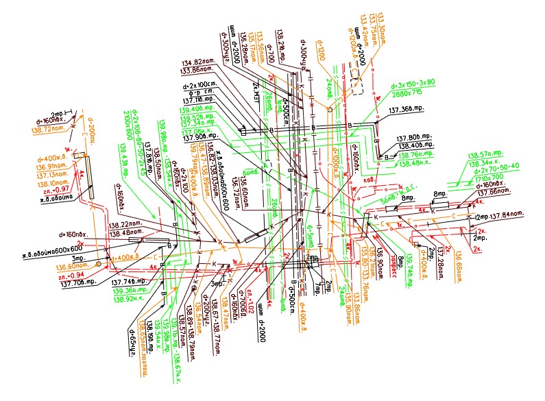
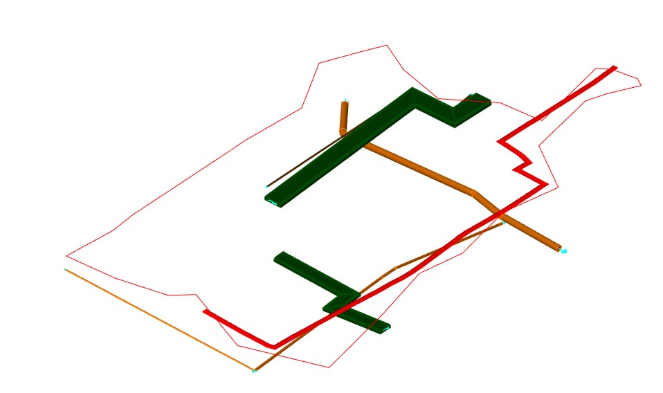
Relief digitization is also carried out in the most user-friendly way and can be implemented in one of two ways: faster and more detailed.
The quick method involves the following steps:
contour creation and triangulation based on elevations of 2D drawings;
import of surfaces from third-party applications of DGN format.
To use the detailed method, you will need:
create a contour (design perimeter);
form an internal contour (site, building);
create an outline of the road / passage / path;
add points (input of elevation marks);
make triangulation (3D surface);
add points of spot elevations, breaklines to the contour (3D-model of the situation).
We have already mentioned the wide functionality of the AWS “External Engineering Networks” and in support of this we will list some of the product’s capabilities. Digitization of existing communications from 2D is carried out by means of a special team; provided the ability to automatically read from the background or manually set the name, type and composition of the object, select a layer for it; the user can set the trajectory for building communication and read heights from the geofence; modeling of existing communications is carried out in the dynamic window for editing the section by objects of arbitrary shape.
And this, we repeat, is only a small part of the proposed tools.
Additionally, it is possible to import existing surfaces and communications from third-party applications by recognizing an XML file. A third-party application exports information about engineering networks in text format: name, location, direction. And we load XML and transform it into a full-fledged 3D model of the existing utility networks.
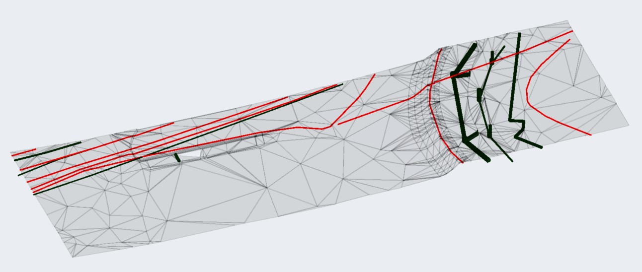
Engineering network design
After a full-fledged digital terrain model has been prepared, the module allows you to start designing the utility network. We run a special command to create a section in which we can add pipes, supports, construction and auxiliary elements from an existing database. The section can also be saved to a database for subsequent reuse.

When the section is formed, we simply draw a plan, indicating the characteristic points of the route. After that, we get a full-fledged engineering network: there is a route, there is a cross-section. Further, it will be possible to add new sections to this trace, change them or save them in the database.

Thus, the technology for constructing a plan for an engineering network provides for:
setting up sections of the utility network route:
selection of pipes from the database,
selection of the location of pipes in the section,
selection of structural elements of the section,
selection of the location of the section elements,
placement of supports;
building a plan:
input of characteristic points on the plan,
input of elevation marks of the utility network relative to the selected surface,
placement of sections along the route;
automatic generation of an information 3D model of the utility network and its saving into a single project database.
This information is sufficient for constructing a longitudinal profile: the corresponding command is called, a pre-configured template for constructing a profile is selected, and the required utility network is indicated. Several different profiles can be built along the same utility network – it depends on the choice of settings. And although the basic settings are offered in the starter kit, we welcome if the user will make the settings based on their own needs.
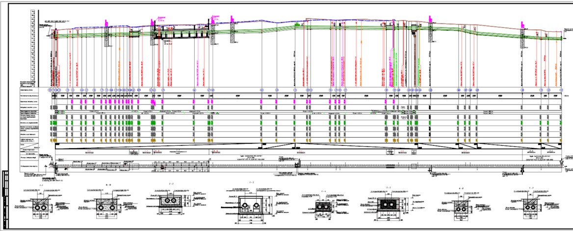
If desired, the longitudinal profile can be inserted on a separate sheet. The profile of the pipe itself and the intersections of all crossed communications are built, their names are displayed, the mark that we crossed, a sub-profile table with characteristic points. The elevations of the utility network are automatically calculated: top, bottom, axis, channel depth, elevation of the bottom of the trench. Slopes are immediately taken into account and angles of rotation are plotted. All this happens automatically, no action is required from the user – you just need to select the utility network and the required command. The profile can be edited – in this case all the marks in the table are recalculated.
Based on the constructed plan of the longitudinal profile network, it is already possible to build a full-fledged three-dimensional model of the entire engineering network – a model of all pipes and structures located in real coordinates relative to the database elements. The three-dimensional model (it is built with a single command) can then be used for auxiliary calculations. Since the model consists of pipes, bends are automatically added at the turning angles. If different pipe diameters are presented in different sections, transitions are automatically added. Reinforcement from the database can be added to pipes. The most successful, in our opinion, function connects a plan, a profile and a three-dimensional model: a change in any of these three components entails a change in the other two. And after placing the supports, we get a full-fledged three-dimensional model of all pipelines and all elements located in the section.
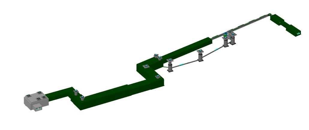
Of course, we did not talk about all the possibilities of “External engineering networks”, but we are sure that this software product will deserve the recognition of users. Moreover, it is constantly developing and improving. It is already planned that for all the functionality it will be possible to display specifications, additional plans, nodes on the drawing, to calculate the strength of the created engineering networks in the START program.
Sergey Sychev,
project support expert
and consulting
Department of Integrated Automation
in construction
CSoft Group
Email: sychev.sergey@csoft.ru


