RET motors for cellular antennas. Optimization for joy
One of the most important tasks of a cellular planning engineer is to optimize the existing network to increase bandwidth and improve the quality of service. This includes, first of all, the fight against noise and interference degrading the capacity of the sector antennas. If the operation of the transceiver is normal, SWR in the antenna-feeder path does not exceed the permissible value, there is no passive intermodulation, and noise and interference do not disappear, then changing the electrical angle of the antenna can help. And since it is not always possible to choose the right optimal value of the tilt angle right away, you have to set different values and based on KPI and collecting statistics of the main parameters of the radio signal, look for the “correct” value. It takes time, and besides, it is quite costly to send a specialist to the base station regularly to change the angle. This can be done remotely if RET – Remote Electrical Tilt is installed on the antennas.

“Electrics” and “Mechanics”
Tilting the antenna is an important action to control the focus of radio communications. The easiest way to manipulate the tilt of the antennas is mechanical, when the antenna is physically positioned at a certain angle to the horizontal plane. Typically, depending on the terrain, antennas at base stations are by default set at 90 degrees (tilt will be considered 0) with respect to the ground. Mechanical control is easier and cheaper to implement, but this often leads to distortion of the radiation pattern due to the influence of structural parts of the infrastructure.
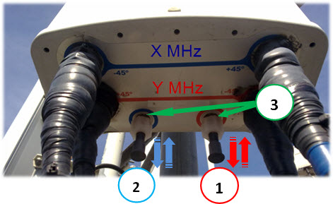
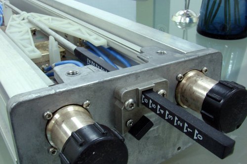
An example of manually set electrical angles. 1 – GSM900 standard, 2 – DCS1800, 3 – electric angle control rod
In cellular networks, the mechanical tilt is almost always fixed, while the electrical tilt is periodically changed. It can be controlled by remote mechanisms and position sensors, which significantly reduces operating costs. Remote electrical tilt angle is abbreviated as RET and is part of an open specification Antenna Interface Standards Group – an interface for controlling antenna devices.
In cellular antennas, the inclination of the electric angle is preferable to the mechanical one, since it does not distort the shape of the radiation pattern in the horizontal plane and the antenna gain, which makes it possible to provide a given concentration of radiation power along the perimeter of the coverage area. The use of purely electrical tilt without mechanical tilt is an attractive choice also for aesthetic reasons when using built-in antennas, antennas camouflaged as trees, or as part of a building structure in public places, etc.
RET mounted additionally
RET built into the antenna itself by the manufacturer
A little about the antenna design
Antennas are produced both with a fixed electric tilt angle and with the possibility of its adjustment on site or remotely. For remote control, as already mentioned, special modules (RET) are used that are connected to the built-in phase shifters. The modules are controlled from the control unit located on the BS (rarely) or from the general network management system, which allows you to dynamically change the tilt angle value depending on the load on a specific sector of the base station.
The modern antenna unit is a group of radiating elements of the antenna array. The distance between the array elements is chosen in such a way as to obtain the smallest level of side lobes of the radiation pattern. The most common lengths of panel antennas are from 0.7 to 2.6 meters (for multi-band antenna panels). The gain ranges from 12 to 20 dBi.
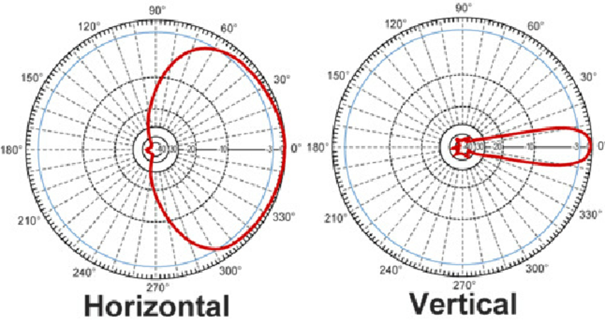
Directional pattern
The fundamental difference between the antennas in organizing the system for adjusting the electrical tilt of the DN is in the design of the adjustable phase shifter. Some manufacturers use linear phase shifters, others rotary.
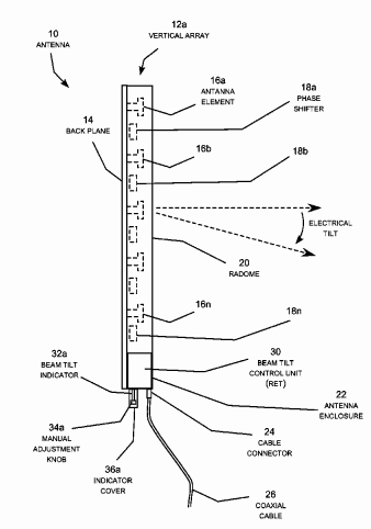
Sector antenna block diagram
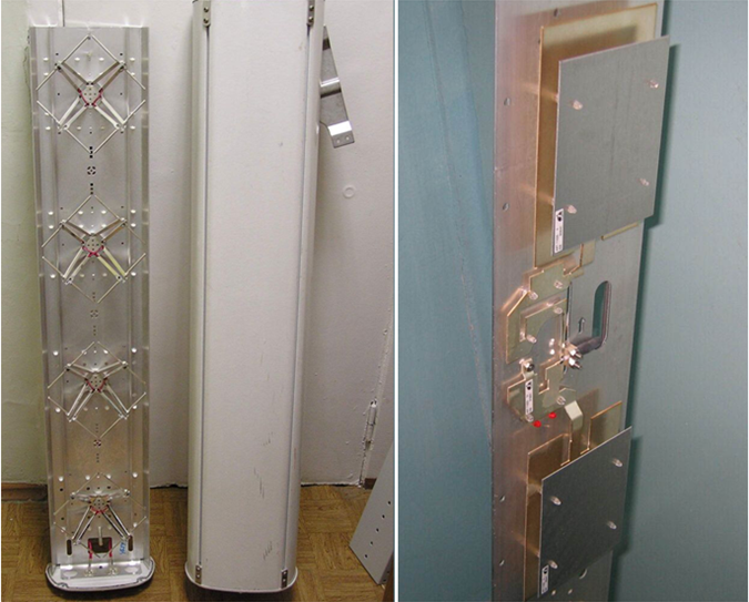
For example, in Powerwave antennas, the regulator is a parallel strip line on a single printed circuit board, over which a dielectric plate moves. When the plate moves, the dielectric constant of the line changes, and, consequently, the speed of wave propagation in it. When a dielectric is introduced into the line, the wave velocity slows down, which leads to a delay in the signal phase and vice versa. The control rod is rigidly connected to the plate, because the linear displacement of the dielectric plate smoothly changes the phase of the power supply of the antenna elements.
Andrew’s antennas use a similar system, but the device consists of individual stripe lines dispersed around the antenna body, actuated by a lever system.
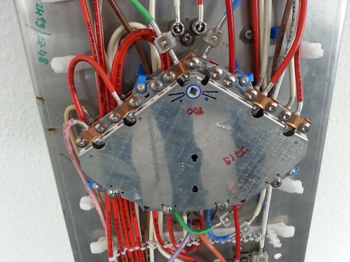
Rotary device for changing the phase of the Kathrein antenna
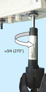
In the design of dipole panel antennas, rotary phase change devices are often found (for example, in Kathrein antennas). The full range of adjustment of the angle of electrical tilt of the antenna pattern corresponds to the angle of rotation of the phase shifter by about 90 °. To “stretch” the adjustment scale, a complex mechanical drive with a lever system (and even a worm gear) is used. This complicates the design of the antenna, reduces the mechanical reliability of the drive, and, most importantly, the accuracy of setting the electrical tilt angle of the antenna pattern.
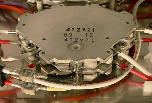
Mechanical drive of the Kathrein antenna phase change device
AISG
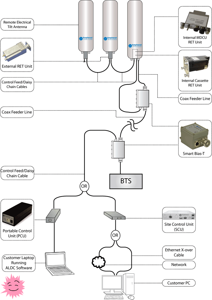
The RET controller sends commands to the motorized antenna driver, which changes the electrical tilt angle by adjusting the phase shifter. The various devices of the RET system are connected to the controller using control cables. Several actuators can be connected either with control cables in series or using junction boxes. The RET system is connected to the base station either through a single control cable or over the RF transmission line through AISG smart tees. All manufactured cellular transmitters (RRU / RSU), which are RET controllers, have AISG ports for connecting RET motors.
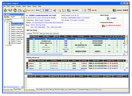
RET monitoring
AISG control cables carry data and power from the controller to the components. Cable lengths range from 0.50 m to 100 m, each cable terminated with male and female connectors.
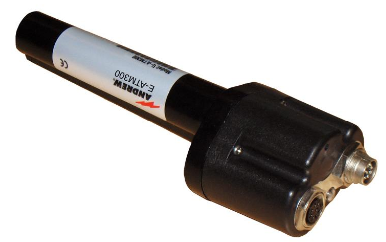
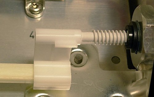
Actuator RET
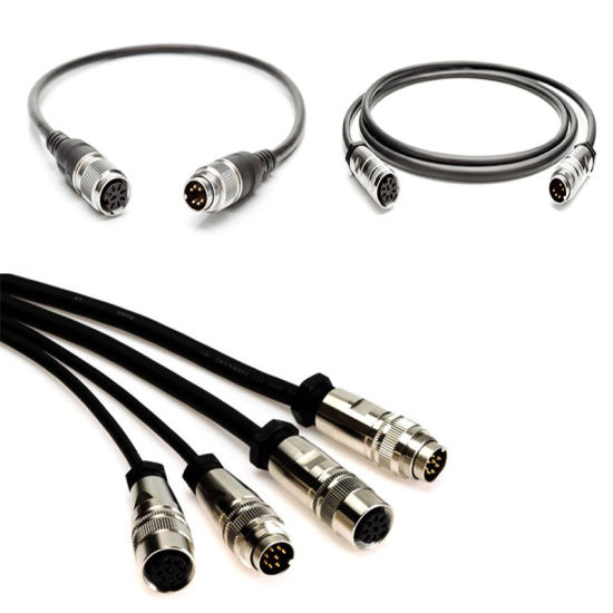
AISG cables
Sometimes mechanical and electrical tilt can be used together to tilt the beam more in one direction to accommodate unusual terrain. And together they can create almost endless combinations. three-dimensional radiation patterns for any situation.
But RET is not the only thing that the AISG standard boasts. The AISG 2.0 standard was released over 10 years ago. During this time, the design of the base stations and the arrangement of antennas at the site have become more complex. It became possible to control and use a multi-band multi-line antenna system for several base stations of the same or different operators. It is possible to change not only the electrical tilt angle, but also remotely change the mechanical angle, as well as the directional azimuth of the antennas.
In November 2018, the AISG 3.0 standard was officially released. AISG version 3.0 also includes functions that already existed in AISG v2.0, but also extensions like RAE (eAntenna), GLS (geolocation sensor) and ASD (leveling sensor device).
Advertising
Our epic servers perfect for any purpose and for representatives of any profession. Creature VDS any configuration within a minute, including servers for storing large amounts of data up to 4000 GB.
Join the our Telegram chat…