Rendering optimization for Mobile
So, let’s get down to the first part.
The development of video cards on desktops and consoles took place in the absence of significant restrictions on power consumption. With the advent of video cards for mobile devices, engineers were faced with the task of ensuring acceptable performance at comparable desktop resolutions, while the power consumption of such video cards should be 2 orders of magnitude lower.
The solution was found in a special architecture called Tile Based Rendering (TBR). To a graphics programmer with experience in PC development, when he gets acquainted with mobile development, everything seems familiar: a similar OpenGL ES API is used, the same structure of the graphics pipeline. However, the tile architecture of mobile GPUs is significantly different from that used on PCs / consoles. “Immediate Mode” architecture. Knowledge of strengths and weaknesses TBR help you make the right decisions and get great performance on Mobile.
The following is a simplified diagram of the classic graphics pipeline used on PCs and consoles for the third decade.

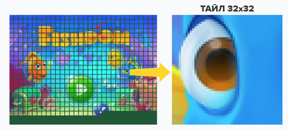
At the geometry processing stage, the vertex attributes are read from the GPU video memory. After various transformations (Vertex Shader) ready-to-render primitives in the original order (FIFO) are passed to the rasterizer, which divides the primitives into pixels. After that, the step of fragment processing of each pixel is carried out (Fragment shader), and the resulting color values are written to the screen buffer, which is also located in the video memory. A feature of traditional architecture “Immediate Mode” is to write the result of the Fragment Shader to arbitrary sections of the screen buffer when processing one draw call (draw call). Thus, for each draw call, access to the entire screen buffer may be required. Working with a large array of memory requires appropriate bus bandwidth (bandwidth) and is associated with high energy consumption. Therefore in mobile GPU began to take a different approach. On the tile architecture typical of mobile video cards, rendering is done in a small piece of memory corresponding to the part of the screen – the tile. The small size of the tile (e.g. 16×16 pixels for Mali video cards, 32×32 for PowerVR) allows you to place it directly on the video card chip, which makes the speed of access to it comparable to the speed of access to the shader core registers, i.e. very fast.
However, since primitives can fall into arbitrary sections of the screen buffer, and a tile covers only a small part of it, an additional step in the graphics pipeline was required. The following is a simplified diagram of how the pipeline works with tile architecture.

After processing the vertices and building the primitives, the latter fall into the so-called instead of sending to the fragment pipeline Tiler. Here the primitives are distributed by tiles, in the pixels of which they fall. After such a distribution, which, as a rule, covers all draw calls directed to one Frame buffer object (aka Render target), the tiles are alternately rendered. For each tile, the following sequence of actions is performed:
- Download old content Fbo from system memory (Load)
- Render of primitives falling into this tile
- Upload new content Fbo to system memory (Store)

It should be noted that Load the operation can be considered as an additional overlay of the “full-screen texture” without compression. If possible, avoid this operation, i.e. prevent switching Fbo “roundtrip”. If before rendering in Fbo all its contents are cleaned, Load the operation is not performed. However, in order to send the correct signal to the driver, the parameters of such cleaning must meet certain criteria:
- Must be disabled Scissor rect
- All color channels and alpha should be allowed.
To not happen Load operation for the depth buffer and stencil, they also need to be cleaned before the start of rendering.
It is also possible to avoid surgery Store for depth buffer / stencil. After all, the contents of these buffers are not displayed in any way on the screen. Before surgery glSwapBuffers can call glDiscardFramebufferEXT or glInvalidateFramebuffer
const GLenum attachments[] = {GL_DEPTH_ATTACHMENT, GL_STENCIL_ATTACHMENT};
glDiscardFramebufferEXT (GL_FRAMEBUFFER, 2, attachments);
const GLenum attachments[] = {GL_DEPTH_ATTACHMENT, GL_STENCIL_ATTACHMENT};
glInvalidateFramebuffer(GL_FRAMEBUFFER, 2, attachments);There are rendering scenarios in which the placement of depth / stencil buffers, as well as MSAA No buffers are required in system memory. For example, if the render in Fbo Since the depth buffer goes continuously, and while the depth information from the previous frame is not used, the depth buffer does not need to be loaded into tile memory before the start of rendering, or unloaded after completion of rendering. Therefore, the system memory can not be allocated for the depth buffer. Modern graphics APIs such as Vulkan and Metal, allow you to explicitly set the memory mode for your counterparts Fbo (MTLStorageModeMemoryless in Metal, VK_IMAGE_USAGE_TRANSIENT_ATTACHMENT_BIT + VK_MEMORY_PROPERTY_LAZILY_ALLOCATED_BIT in Vulkan)
The implementation deserves special attention MSAA on tile architectures. High Resolution Buffer for MSAA does not leave tile memory due to partitioning Fbo to more tiles. For example, for MSAA 2×2 tiles 16×16 will be resolved as 8×8 during Store operations i.e. In total, you will need to process 4 times more tiles. But additional memory for MSAA is not required, and due to the render in fast tile memory there will be no significant restrictions on bandwidth However use MSAA on tile architecture increases the load on Tiler, which can negatively affect the rendering performance of scenes with a lot of geometry.
Summarizing the above, we present the desired scheme of working with FBO on the tile architecture:
// 1. начало нового кадра, рендерим во вспомогательный auxFBO
glBindFramebuffer(GL_FRAMEBUFFER, auxFBO);
glDisable(GL_SCISSOR);
glColorMask(GL_TRUE, GL_TRUE, GL_TRUE, GL_TRUE);
glDepthMask(GL_TRUE);
// glClear, который гарантированно очистит все содержимое
glClear(GL_COLOR_BUFFER_BIT | GL_DEPTH_BUFFER_BIT |
           GL_STENCIL_BUFFER_BIT);

renderAuxFBO();

// содержимое буфера глубины/трафарета не нужно копировать в системную память
glInvalidateFramebuffer(GL_FRAMEBUFFER, 2, depth_and_stencil);
// 2. Рендер основного mainFBO
glBindFramebuffer(GL_FRAMEBUFFER, mainFBO);
glDisable(GL_SCISSOR);

glClear(...);
// рендер в mainFBO с использованием содержимого auxFBO
renderMainFBO(auxFBO);

glInvalidateFramebuffer(GL_FRAMEBUFFER, 2, depth_and_stencil);
If you switch to render auxFBO in the midst of formation mainFBO, you can get extra Load & store operations that can significantly increase the formation time of the frame. In our practice, we encountered a slowdown in rendering even in the case of idle FBO settings, i.e. without the actual render in them. Due to the architecture of the engine, our old circuit looked like this:
// холостая установка mainFBO
glBindFramebuffer(GL_FRAMEBUFFER, mainFBO);
// ничего не делается
glBindFramebuffer(GL_FRAMEBUFFER, auxFBO);
// формируем auxFBO
renderAuxFBO();

glBindFramebuffer(GL_FRAMEBUFFER, mainFBO);
// начинаем рендер mainFBO
renderMainFBO(auxFBO);
Despite the lack of gl calls after the first installation mainFBO, on some devices we got extra Load & store operations and worse performance.
To improve our understanding of overhead from using intermediate Fbo, we measured the loss of time switching full-screen Fbo using synthetic dough. The table shows the time spent on Store operation during multiple switching Fbo in one frame (the time of one such operation is given). Load the operation was absent due to glClear, i.e. a more favorable scenario was measured. The permission used on the device contributed. It could more or less correspond to the power of the installed GPU. Therefore, these figures give only a general idea of how expensive the switching of targets on mobile video cards of various generations is.
| GPU | milliseconds | GPU | milliseconds |
|---|---|---|---|
| Adreno 320 | 5.2 | Adreno 512 | 0.74 |
| PowerVR G6200 | 3.3 | Adreno 615 | 0.7 |
| Mali-400 | 3.2 | Adreno 530 | 0.4 |
| Mali-t720 | 1.9 | Mali-g51 | 0.32 |
| PowerVR SXG 544 | 1.4 | Mali-t830 | 0.15 |
Based on the data obtained, we can come to the recommendation not to use more than one or two FBO switches per frame, at least for older video cards. If the game has a separate code pass for Low-End devices, it is advisable not to use the FBO change there. However, on the Low-End, the issue of lowering the resolution often becomes relevant. On Android, you can lower the rendering resolution without resorting to using intermediate FBO by calling SurfaceHolder.setFixedSize ():
surfaceView.getHolder().setFixedSize(...)
This method will not work if the game is rendered through the main Surface applications (typical scheme of work with Nativeactivity) In case of using the main Surface reduced resolution can be set by calling the native function ANativeWindow_setBuffersGeometry.
JNIEXPORT void JNICALL Java_com_organization_app_AppNativeActivity_setBufferGeometry(JNIEnv *env, jobject thiz, jobject surface, jint width, jint height)
{
ANativeWindow* window = ANativeWindow_fromSurface(env, surface);
ANativeWindow_setBuffersGeometry(window, width, height, AHARDWAREBUFFER_FORMAT_R8G8B8X8_UNORM);
}
In Java:
private static native void setBufferGeometry(Surface surface, int width , int height );
...
// в наследнике SurfaceHolder.Callback
@Override public void surfaceChanged(SurfaceHolder holder, int format, int width, int height)
{
     setBufferGeometry(holder.getSurface(), 768, 1366); /* ... */
...
Finally, we mention the convenient ADB command for controlling selected surface buffers on Android:
adb shell dumpsys surfaceflinger
You can get a similar conclusion that allows you to estimate the memory consumption for surface buffers:

In the screenshot above, the system selects 3 buffers for triple buffering GLSurfaceView games (highlighted in yellow), as well as 2 buffers for the main Surface (highlighted in red). In the case of rendering through the main Surface, which is the default scheme when using Nativeactivityallocating additional buffers can be avoided.
That’s all for now. In the following articles, we will classify mobile GPUs, as well as analyze methods for optimizing shaders for them.