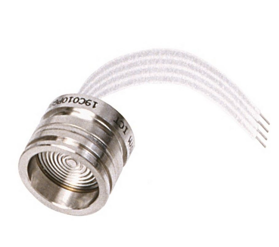
Recovery of pressure sensor Honeywell 19 mm Series
Brief background. I have been developing electronics for a fatigue stand where stents are tested. Stand for stents – music for the speaker’s ears and cognitive dissonance for the first time hearing these words. Since it is necessary to imitate a person’s heartbeat, it is necessary to provide a pressure drop, but in order to control something, it is desirable to measure it somehow.
The installer has tested a stack of stents with varying success. One of the factors of “variability” of success was a failed gauge pressure sensor 19C015PG1K… I don’t presume to talk about the quality of these cheap (no) sensors, but reverse engineering and restoration were carried out from three failed sensors (and only one of them died due to objective reasons – they pierced the membrane, the rest died during rather careful operation) …

The sensor has a very fragile cable attached to a fragile ceramic board, with a slight bend of which one of two things happens: a microcrack is formed in the place where the cable and the board are soldered, which is difficult to detect and incredibly difficult to solder back, or you lucky and the cable is soldered very high quality, so it takes with it a part of the ceramic board (see photo). By the way, the cable is made of paper (why not, the sensor is just $ 350 +).


I got the idea that the sensor works on the principle of a bridge meter. I just didn’t understand why the Winston Bridge needs 6 legs that haven’t called each other yet.
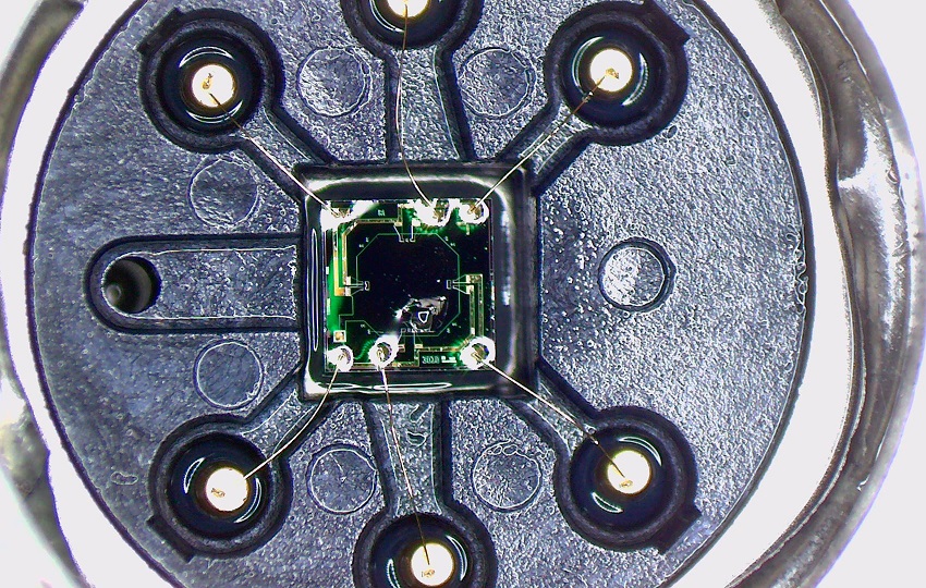
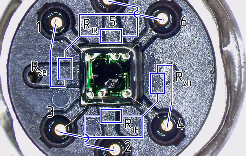
Having opened the sensor, which had a damaged membrane, I found that these are 2 pairs of resistors, located symmetrically and not closed in a bridge. OK, 6 legs is justified. The sensing element itself floats in an oily buffer liquid.
Sketching what we saw, making measurements by unsoldering the ceramic board.
I marked the resistor pairs as Top and Bottom and numbered the legs so as not to get confused, because the ceramic board is mirrored in relation to this view.
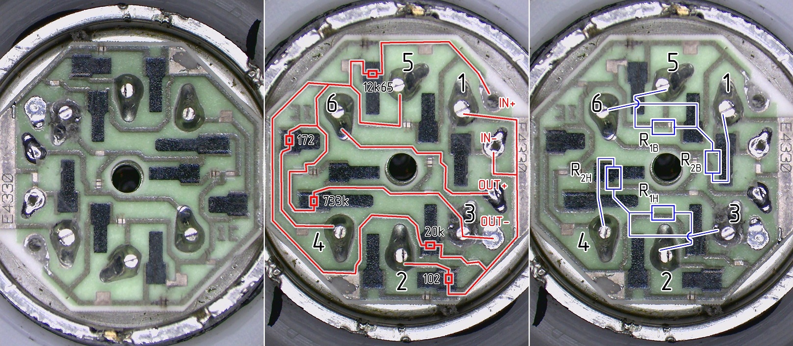
I removed the ceramic board and measured the resistances. For clarity, to make it easier to restore the circuit, I painted over the photograph.

It took some time to turn the drawings into something readable, and that’s what I ended up with.
Having recreated the circuit on the breadboard, we get a working sensor. More reliable than factory performance. Why is the performance so … bad? I can assume that the sensor is calibrated after mounting the ceramic board. in fact, it is a complex SMD resistor, i.e. you can see how the resistances are adjusted by the laser, unnecessary connections are cut. Perhaps ceramic is better in terms of temperature stability in conjunction with this sensor. I do not know, but now I know how to fix it and I share it here.
Hope these materials help someone save time and / or money. Well, or at least a little entertained.


