Projecting the position of objects from a CCTV camera onto a map using only school geometry
Introduction
Is it possible to turn the coordinates on the image into specific geographical coordinates? Despite the fact that this sounds somewhat unusual, such a conversion is quite possible.
Today I will talk about how you can project coordinates from a flat image to a map. This short article will be a kind of continuation of the first articles, in which I talked about the basic capabilities of Mask R-CNN.
This article was written in collaboration with @avdosev, for which many thanks to him.
Problem
It is necessary to understand from the image from the camera where the object is located on the map of the territory. Schematically it looks like this.

In the image, each object is inscribed in a rectangle, this is not accidental, in the future we will use this rectangle to get the desired pixel for the object.
We will also agree that we are considering a simple case when the camera does not cross the walls, and we can represent its field of view when viewed from above as a trapezoid.
Camera requirements:
Must not be fish eye…
Image requirement:
The camera image should show the ground plane.
Method 1.
You can set the corresponding terrain coordinate for each pixel of the image. If it is necessary to find out the geo-coordinate, we just get it by the associated pixel.
Advantages:
The algorithm will work quickly, we are limited by the speed of access to the Map data structure, file or database;
There are no complicated calculations in runtime.
Disadvantages:
If the camera moves even by a millimeter, all our data will become outdated and will no longer give an accurate result;
It is required to store information about each pixel for each camera on the territory, which is impractical;
Setting coordinates for each pixel is too long and difficult.
Based on these problems, the first method was discarded and the search for others continued.
Method 2.
Given the coordinates of the corners of the camera’s field of view, you can calculate the coordinates for the supplied pixel. They can be obtained in two ways:
Look at the map of the territory and images from the camera and try to indicate the most accurate coordinates of the corners;
Knowing the camera parameters (height above the ground, camera coordinates, camera tilt angle and viewing angles), get the coordinates of the angles of visibility (trapezoid), or immediately calculate the coordinates of the object.
Calculation of the position of the object by the coordinates of the angles of visibility
First, you need to figure out what the camera’s field of view looks like in the top view.

To work with this area, you need to drop the part of the flat cone next to the camera, which I marked in red in the picture above. This area is selected based on the fact that objects cannot (or should not) get into the red zone.

For simplicity of calculations, it can be considered a trapezoid.

To calculate the location of the object, we use the following formulas.


Where
l2 , lone – intermediate variables for the top;
imageHeight, imageWidth – height and width of the image from the camera in pixels, respectively;
A, B, C, D – geographic coordinates of the trapezoid vertices of the camera’s field of view in the format {lat: float, lng: float};
X, Y – coordinates of pixels on the image in the Cartesian coordinate system, are integers;
M are the resulting coordinates.
In the case of a Full HD picture, the width and height will be as follows: imageHeight = 1080; imageWidth = 1920.
After recognizing the object in the image, the neural network will return the coordinates of the corners of the rectangle. From it it is necessary to select a point on the image for which the coordinates will be determined. There are several ways to do this:
Take rectangle centroid;
Take the middle of the bottom side of the rectangle. This method will give a more accurate result if the object is moving on the ground rather than flying;
All this can be combined:
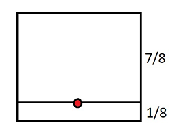
Take the 1 / N height and the horizontal center, where N can vary depending on various factors, such as the type of object or how you move.
For example, for N = 8 we will get such a resulting point on the object’s rectangle.
All these methods have a significant error at a low height of the camera and / and at a large tilt of the camera.
Calculating camera viewing angles using its characteristics
To find points A, B, C, D in an automated way, we need to find the center of the future trapezoid C.
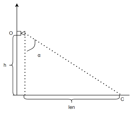
Knowing the height h and the angle of inclination of the camera α, we can find the opposite leg len…

Knowing the coordinates of the camera (point O) and its direction (in which direction it is looking, angle β), you can find the center of its observation (point C). You can find it by the formula:


Measuring the angle α and β can be difficult in practice. To avoid difficult measurements, you can estimate the approximate coordinate of the C point (center of the image), and calculate the angles.

In order to find the coordinates of the corners of the image, it is necessary to know the angles of the camera view horizontally and vertically. By looking at the viewing angles in the characteristics of the camera, we can find the coordinates. Calculations are performed in the same way as for the center point. In this case, it is necessary to make an offset.
For main angle α +/- half the vertical viewing angle.
For the secondary angle β +/- half the horizontal viewing angle.
Let us take the horizontal viewing angle as viewAngleHorizontal, and vertical for viewAngleVertical.
For points that are closer to the camera, we will subtract half of the viewing angle, and for those farther away, we will add.
Next, consider the points of the trapezoid again. (Do not confuse the next point C with the center point).


By combining the offsets at the viewing angles, we get the coordinates of the image corners – points A, B, C, D.
Knowing the points A, B, C, D, you can get the geographic coordinates of the object. But you can do without them. The next calculation will require imageHeight, imageWidth, X, Y…
If we add auxiliary axes, where the coordinates X, Y are the center, then our pixel will divide the image into 4 parts. Having determined the ratios of the parts horizontally and vertically, we can determine the angles by which the displacement should be done. The final formula looks like this:


Python implementation
imageWidth = 1920 # в данном примере зададим их константами
imageHeight = 1080
import numpy as np
def geoToList(latlon):
return np.array((latlon['lat'], latlon['lng']))
def listToGeo(latlon):
return {'lat': latlon[0], 'lng': latlon[1] }
def getGeoCoordinates(A, B, C, D, X, Y):
A, B, C, D = list(map(geoToList, [A, B, C, D]))
vBC = (C - B) / imageHeight
vAD = (D - A) / imageHeight
latlonPixel1 = vBC * (imageHeight - Y) + B
latlonPixel2 = vAD * (imageHeight - Y) + A
vM = (latlonPixel2 - latlonPixel1) / imageWidth
M = vM * X + latlonPixel1
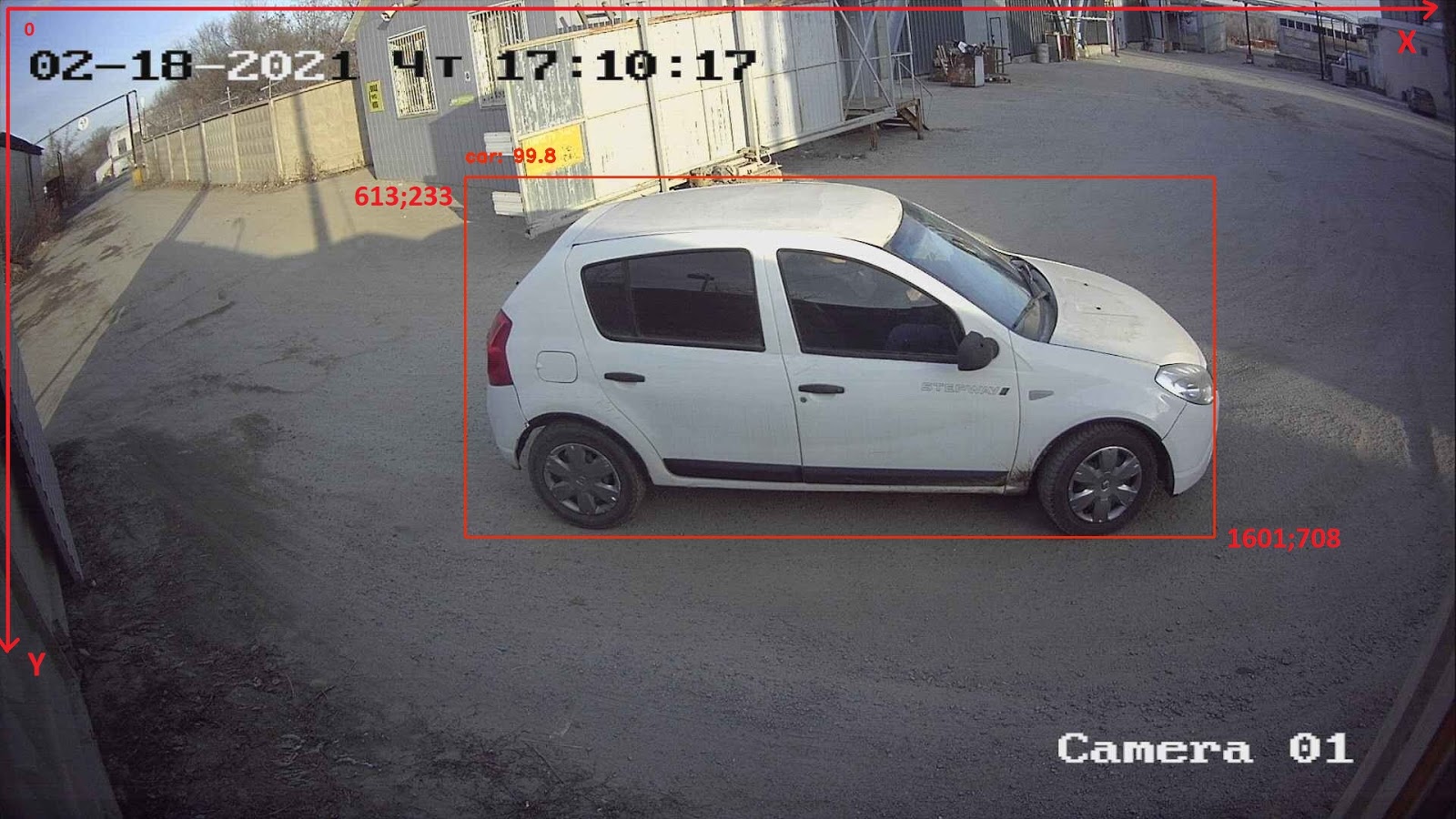
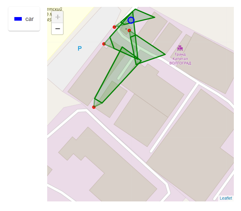
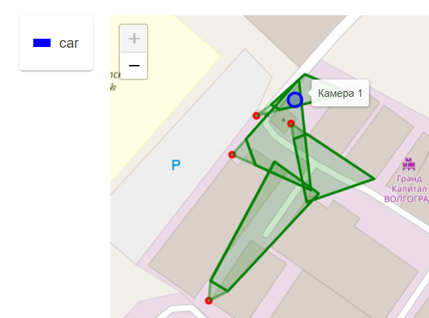
return listToGeo(M)results
From this image, the coordinates of the objects of the upper left and lower right corners in X, Y, respectively, were obtained – 613; 233 1601; 708.
Source always available on Github.
If you find errors in the algorithm or in the formulas, please let us know in the comments.