Load Detect (or how to detect vandalism)
In this text, I wrote how to diagnose and test an electrical circuit such as an H-bridge. Programming the H-bridge is easy. It is much more difficult to determine Fault (s) in this notorious H-bridge in Run-Time (e) in order to turn off the keys in time and put the entire circuit in a safe state, thereby saving expensive equipment from burning.
A bit of theory
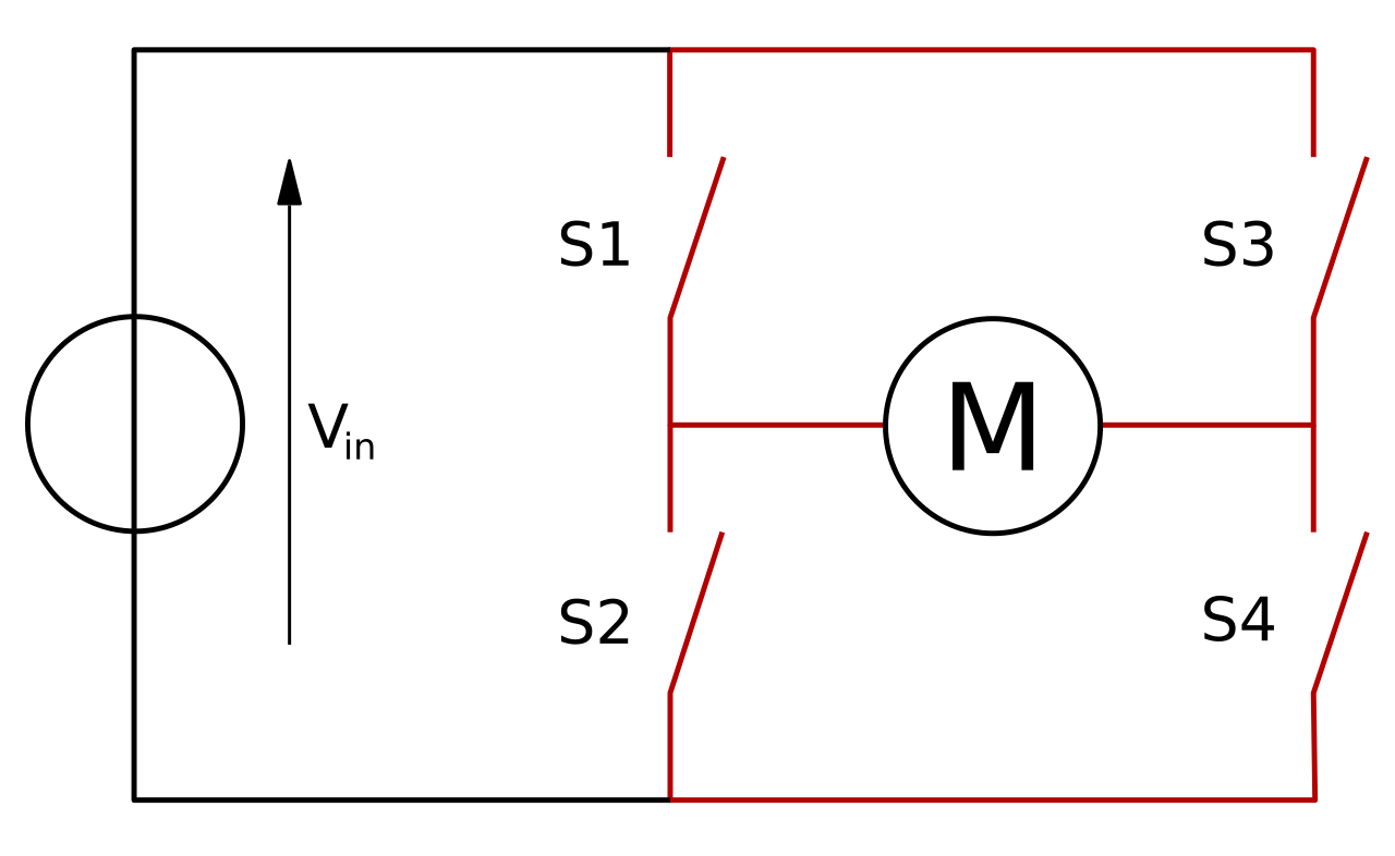
In electronics, there is a classic electrical circuit called the H-bridge.

This circuit allows you to pass current through the load in 2 directions: along or across the load. If a DC motor is connected to this circuit, it will spin either clockwise (CW) or counterclockwise (CCW). You can also modulate the current value if you switch the keys on a PWM signal
H-bridges are actively used in devices that turn stepper motors in CNC machines in glass lift controllers (spinner firmware), to control car headlights, and so on.
There is a problem. Rather, there are 31 problems. That is, there can be 31 types of failures in H-bridges, which will lead to the fact that the H-bridge simply will no longer work. And 14 cases will lead to the fact that sparks will simply fall from the H-bridge. Here is a list of those failures.
How to detect crashes in the H-bridge at runtime? We need to develop a mechanism that can be called Load Detect.
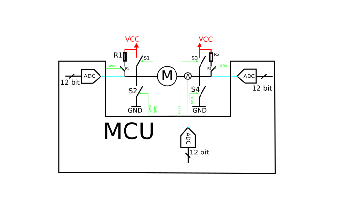
It is clear that the H-bridge must be somehow observed. In electronics, there are only 2 ways to monitor anything: GPIOs working as an input and ADC. Here is a possible circuit design that will allow you to diagnose the condition of the H-bridge. Here, an analog-to-digital converter (ADC) is connected to each arm of the H-bridge and there is also a key that controls the voltage pull-up to the power supply.
pbc 3. H-bridge monitoring scheme
Each microcontroller has analog pins that are connected to an internal ADC converter. The voltage pull-ups to the power supply can be controlled via GPIO or using a key and a high-ohm resistor or using special source chips. wetting current.

It is obvious that some algorithm or a high-level software state machine that will report when an error occurs in the H-bridge. Ideally, I would like a separate ASIC to do this. But you can also sprinkle a purely software solution.
The development of a state machine is just a mechanical operation. As you know, any finite state machines are designed in 7 phases:
Phase | State machine development stage |
1– | define exits |
2– | define states |
3– | define actions |
four– | define inputs |
five– | compose table transitions |
6– | draw graph transitions |
7– | to embody state machine in code |
1– Here exits state machine diagnostics of the H-bridge. These are just those high-level events that the user wants to hear (circuit designer, programmer, technician, integrator, driver)
No. | FSM Output |
1 | left shoulder short GND |
2 | left shoulder short |
3 | right shoulder short GND |
four | right shoulder short |
five | open load |


