Kafka as a data warehouse: a real-world example from Twitter
We have long been interested in the topic of using Apache Kafka as a data warehouse, considered from a theoretical point of view, for example, here. It is all the more interesting to bring to your attention a translation of material from the Twitter blog (original – December 2020), which describes an unconventional use of Kafka as a database for processing and reproducing events. We hope the article will be interesting and give you fresh thoughts and solutions when working with Kafka…
Introduction
When developers consume publicly available Twitter data through the Twitter API, they rely on reliability, speed, and stability. Therefore, some time ago, Twitter launched Account Activity Replay API for Account Activity API to make it easier for developers to ensure the stability of their systems. The Account Activity Replay API is a data recovery tool that allows developers to retrieve events that are up to five days old. This API recovers events that were not delivered for various reasons, including server crashes that occurred while attempting to deliver in real time.
Twitter engineers have strived not only to create APIs that will be well received by developers, but also to:
- Increase the productivity of engineers;
- Make the system easy to maintain. In particular, to minimize the need for context switching for developers, SRE engineers and everyone else who deals with the system.
For this reason, when working on creating a replay system that relies on for the API, it was decided to take as a basis the existing system for working in real time, on which the Account Activity API is based. In this way, it was possible to reuse existing developments and minimize context switching and training, which would be much more significant if a completely new system were created for the described work.
The real-time solution is based on a publish-subscribe architecture. For this purpose, taking into account the tasks and creating the level of information storage from which it will be read, the idea arose to rethink the well-known streaming technology – Apache Kafka.
Context
Events occurring in real time are produced in two data centers. When these events are triggered, they are written to publish-subscribe topics that are cross-replicated across two datacenters for redundancy.
Not all events are required to be delivered, so all events are filtered by an internal application that consumes events from the relevant topics, checks each against a set of rules in the key and value store, and decides whether the event should be delivered to a specific developer via a public API. Events are delivered via a webhook, and each webhook URL belongs to a developer identified by a unique ID.
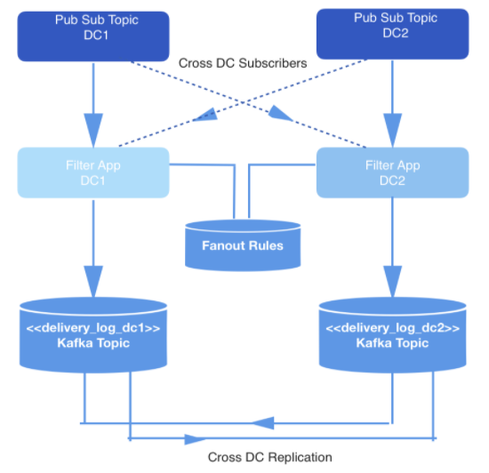
Figure: 1: Data Generation Pipeline
Storage and segmentation
Typically, when building a playback system that requires such a data store, an architecture based on Hadoop and HDFS is chosen. In this case, on the contrary, Apache Kafka was chosen, for two reasons:
- The system for working in real time was on a publish-subscribe principle, organic to the Kafka device
- The amount of events that needs to be stored in the playback system is not in petabytes. We store data for no more than a few days. Also, dealing with MapReduce jobs for Hadoop is more expensive and slower than consuming data in Kafka, and the first option does not meet developer expectations.
In this case, the main load falls on the real-time data playback pipeline to ensure that the events that need to be delivered to each developer are stored in Kafka. Let’s call the topic Kafka delivery_log; there will be one such topic for each datacenter. These topics are cross-replicated for redundancy, which allows a replication request to be issued from a single datacenter. Events stored in this way are deduplicated before delivery.
In this Kafka topic, we create many partitions using the default semantic sharding. Therefore, partitions correspond to the developer’s webhookId hash, and this id serves as the key for each entry. It was supposed to use static sharding, but in the end it was abandoned due to the increased risk that one partition will contain more data than others, if some developers generate more events in the course of their activities than others. Instead, a fixed number of partitions were chosen to distribute the data over, and the sharding strategy was left at the default. This reduces the risk of unbalanced partitions and does not have to read all partitions in the Kafka topic.
In contrast, based on the webhookId for which the request is made, the replay service determines the specific partition to read from, and raises a new Kafka consumer for that partition. The number of partitions in a topic does not change, since key hashing and event distribution depend on it.
To minimize the storage space, the information is compressed using the algorithm snappy, since it is known that most of the information in the described task is processed on the consumer side. Plus, snappy gives in faster decompressionthan other compression algorithms supported by Kafka: gzip and lz4…
Inquiries and processing
In a system designed this way, the API sends replay requests. As part of the payload of each validated request comes a webhookId and a range of data for which events should be played. These queries are stored in MySQL for a long time and are queued until they are picked up by the replay service. The data range specified in the request is used to determine the offset at which to start reading from disk. Function offsetForTimes object Consumer used to get offsets.
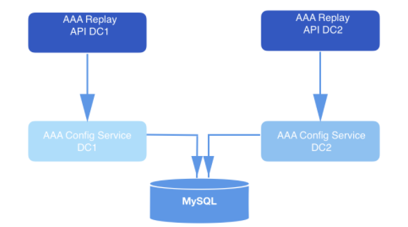
Figure: 2: Playback system. It receives the request and sends it to the configuration service (data access layer) for further long-term storage in the database.
Replay service instances handle each replay request. The instances are coordinated with each other using MySQL to process the next replay record stored in the database. Each replay worker process polls MySQL periodically to see if there is a job to process. The request goes from state to state. A request that has not been picked up for processing is in the OPEN state. The request that has just been dequeued is in the STARTED state. The request currently being processed is in the ONGOING state. A request that has undergone all transitions is in the COMPLETED state. The replay workflow only picks up requests that have not yet started processing (that is, those in the OPEN state).
Periodically, after the worker process has removed the request from the queue for processing, it is tapped into the MySQL table, leaving timestamps and thereby demonstrating that the replay job is still being processed. In cases where the reproducing workflow instance dies before it finishes processing the request, these jobs are restarted. Consequently, the reproducing processes dequeue not only requests in the OPEN state, but also pick up those requests that were transferred to the STARTED or ONGOING state, but did not receive any feedback in the database after a specified number of minutes.
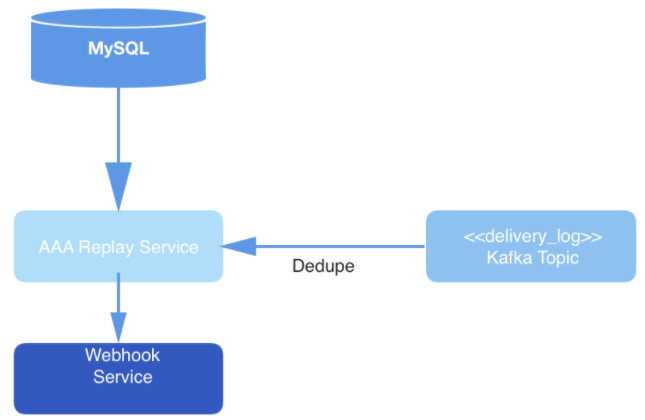
Figure: 3: Data delivery layer: the replay service polls MySQL for a new request processing job, consumes the request from the Kafka topic, and delivers events through the Webhook service.
Eventually, events from the topic are deduplicated in the process of being read, and then published to the URL of a specific user’s webhook. Deduplication is performed by maintaining a cache of read events, which are then hashed. If an event with a hash that is identical to which is already in the hash comes across, then it will not be delivered.
In general, this use of Kafka is not traditional. But within the framework of the described system, Kafka successfully works as a data store and participates in the work of the API, which contributes both to the usability and ease of access to data when recovering events. The strengths of the system for real-time operation came in handy in the framework of such a solution. In addition, the rate of data recovery in such a system fully meets the expectations of the developers.