how the Selectel network developed

Today, Selectel combines six of its own data centers in Moscow, St. Petersburg and the Leningrad region. And two more partnerships – in Novosibirsk and Tashkent.
At the beginning of the company’s development, everything was different: the first data centers were highly dependent on each other, and there were delays in communication channels when Moscow outlets accessed the Internet. This was due to the suboptimal network architecture, which we then completely rebuilt.
In the article we tell what problems we encountered during the opening of new data centers and how we came to modern redundancy schemes.
Multiple data centers, one router and minimum redundancy
In 2009, Selectel had only two data centers – Tsvetochnaya-1 and rented by Technodom on Vasilyevsky Island.
We provided access according to the standard scheme, when servers are connected to the router through access switches and aggregation. But even then there was a problem: there were several data centers, and there was only one router – it was located on Tsvetochnaya-1. Optical communication lines were extended to it from Technodom along different routes – then this was the minimum redundancy that we could provide.
The network layout did not suit us: interruptions in the work of the Tsvetochnaya-1 data center could affect the clients of Technodom.
Opening of new data centers
The situation with the lack of backup routers worsened when in 2009-2010 we launched three buildings with computer rooms in the Leningrad region, Dubrovka village. With the advent of the latter, the Technodom was closed – we completely left from there. VKontakte also moved to a new data center.
Even with the opening of the first Moscow data center on Berzarina, the router was only on Tsvetochnaya-1. The result – delays of 10-12 ms between Moscow and St. Petersburg, as well as a strong “dependence” between the regions.
Redundancy of aggregation switches and links
In 2010, we lacked the skills and hands to rebuild the network layout. Therefore, at first we took care of redundant aggregation switches – for this we used Stack technology.
It was not possible to completely get rid of failures: Stack could fall even due to software updates on the switches. Also, this technology had other problems – they were discussed in more detail in last article.
In addition, we have reserved connections throughout the network. In addition to double links between access and aggregation switches, two cables were laid between Dubrovka and Tsvetochnaya. We did this along two railways – the upper and lower tracks.

Network diagram, 2010.
Between Moscow and St. Petersburg, two leased lambs of 10 GB each were connected – such a network scheme existed until 2016. But the problem of “dependence” between regions has not gone away.

Enabling Backup Routers
With the opening of the Tsvetochnaya-2 data center in 2015, the need for a backup router reached its peak. And the device was already in the warehouse, but we did not know how to install and configure it in order to achieve the required level of fault tolerance. Considered several options.
Option 1. Place the router on Tsvetochnaya-2.
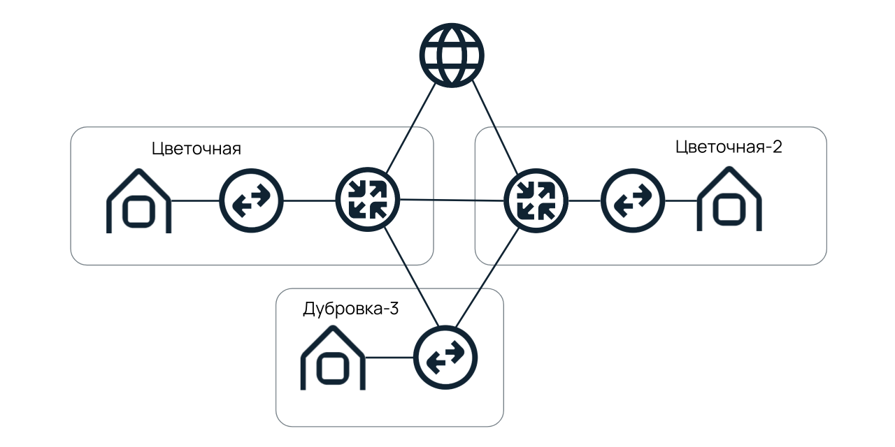
At first glance, everything is fine: Tsvetochnaya-1 and Tsvetochnaya-2 have their own Internet access points. Between the first and second buildings there is its own optics, and from Dubrovka there are cables along the upper and lower railways. But, looking closely, we found cons.
- There are no alternative telecom operators on Tsvetochnaya-2 – most of their optical cables go to Tsvetochnaya-1. And it turned out that the data from the router on Tsvetochnaya-2 was still transmitted through Tsvetochnaya-1.
- The scheme is subject to the meteorite factor. The routers are geographically close. If electricity is cut off in the Tsvetochnaya-1 area or a meteorite falls, the consequences will affect Tsvetochnaya-2 and, as a result, Dubrovka.
Option 2.
Locate the router at a remote operator site.
So we subsequently did: we installed a backup router at Kantemirovskaya, 12.
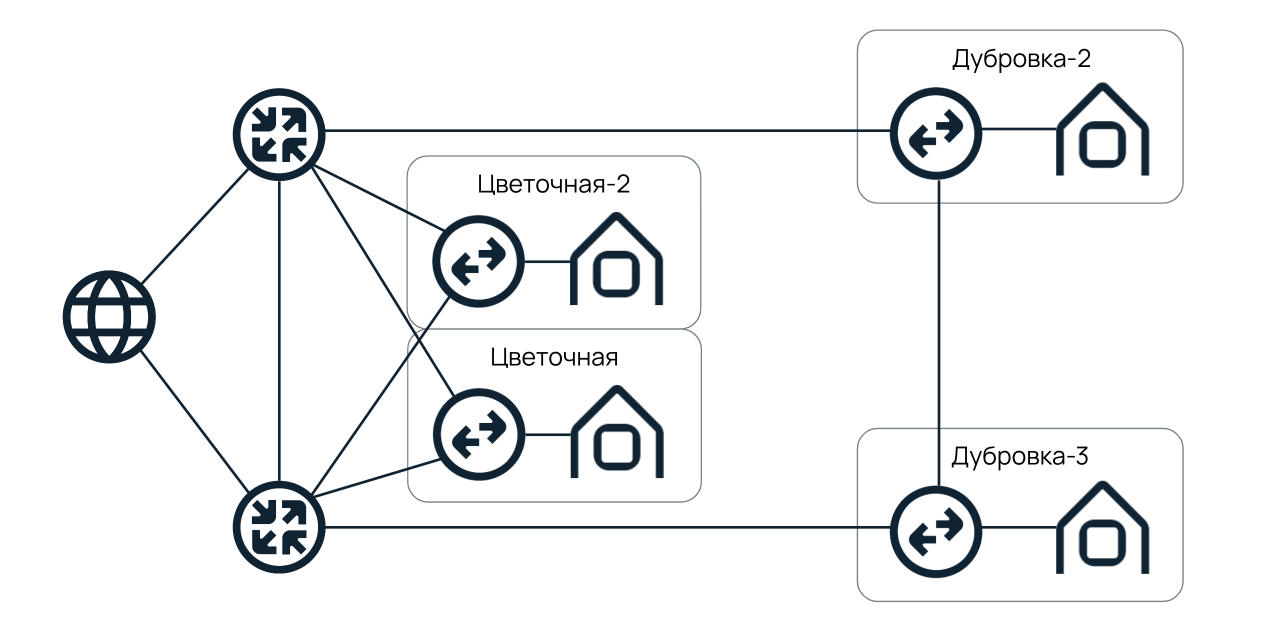
We had two optical cables between Tsvetochnaya and Dubrovka. One from Tsvetochnaya-1 in the direction of Kantemirovskaya and Dubrovka, and the second – immediately to Dubrovka, through the lower railway. Previously, these cables provided redundancy at the level of an aggregated communication channel, but now they are connected to independent border routers.
Network diagram in Moscow
With the increase in the number of racks in Moscow, we switched to a scheme similar to St. Petersburg: on the second and fourth floors, Berzarin was installed using a router. They were also connected to the DataPro data center on Aviamotornaya, where we still rent racks.
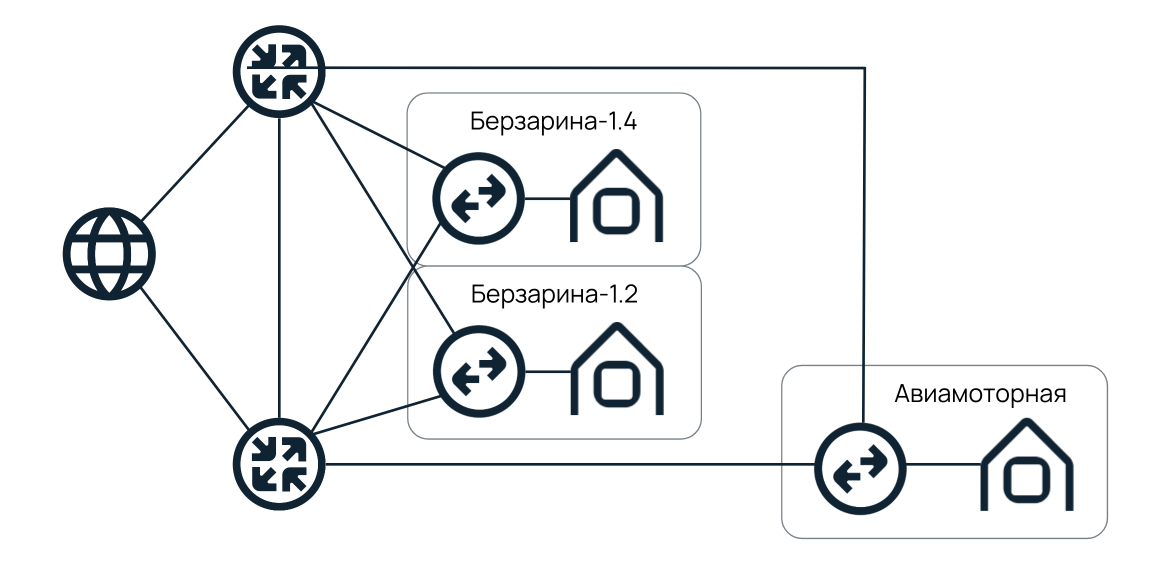
Until now, we adhere to this network scheme. But the plans for the next few years are to repeat the experience of St. Petersburg. And when building a new data center in Moscow, spread the border routers in such a way as to minimize the meteorite factor.
You may also be interested in these texts:
→ NaaS satellite: how we wanted to fly into space and eventually connected the cloud with “iron” servers through a global router
→ How we got frustrated with Haskell and learned how to run regions in a few days
→ Network redundancy in data centers: solving the problem about two cyclists
Network diagram in other regions
In 2018-1019, we started opening data centers in other regions. We decided that we would immediately make them independent from Moscow and St. Petersburg: we organized a typical network scheme and installed two routers in each of the data centers.
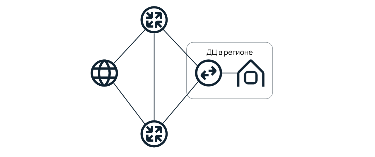
Today, Tashkent and Novosibirsk are built according to this scheme.
The independence of the regions makes it possible to divide the network planes and provide a stable Internet access to a larger number of customers. For example, when routers were installed only at Tsvetochnaya-1, we could support about 2,500 clients from Moscow and St. Petersburg. Now – the same number, but already in each of the data centers.
Redundancy of access switches
We use only one access switch and a link to connect to the server. This is justified by saving ports: each server has three network cards installed. The first is responsible for enabling IPMI, the second is for connecting to the Internet, and the third is for connecting to the local network. AT
with a ready-made configuration, this scheme is already “embroidered” and active from the moment the devices are installed in the rack. So customers do not overpay for extra network cards.
For some customers who need to increase the level of fault tolerance, we offer MLAG redundancy. More information about the technology can be found in the previous article.
Differences between projects
Within the network of one data center, it was necessary to achieve independence between projects. So that an accident, for example, in a VPC does not affect the performance of dedicated servers. To do this, we installed two access routers above the aggregation switches responsible for each of the projects. The result is a typical scheme:

Upstairs there are two border routers – “Tsvetochnaya-1” and Kantemirovskaya, 12. Links are extended to them from access routers that provide Internet access for specific projects. With the help of such a scheme, it was possible to divide the network planes in such a way that the probability of the simultaneous fall of several projects was minimal.
What plans do you have for the future?

Kirill Malevanov
CTO Selectel
We started with data centers with 200-250 racks. Now we are building computer rooms for 500-600 racks, the plans are for 2000. Accordingly, if today up to 2500 clients in each location can use dedicated servers, then in the future we want to increase this number by at least 10 times.
Also, after the commissioning of a new data center on Yurlovsky Proezd, we plan to install one of the border routers there and launch a new independent Internet access point.