Homemade ship roll and trim meter

One of the instruments needed on various ships is the inclinometer-trim. It is needed in order to know exactly how the ship is rocking, and whether it is time to do something to reduce this pitching (well, or to get off the ship in time, like a ship’s rat). The development of such devices is a rather rare task, but I still ran into it, and decided to try to make my own implementation of a prototype of such a tilt trimmer. Under the cut, I will offer you an option for manufacturing such an electronic inclinometer-trim, as I now see its possible implementation.
As I pointed out above, the usefulness of a krenodifferentometer for a ship is obvious. And this means that inclinometers (well, or only inclinometers) have been produced for a long time. Moreover, both mechanical and electronic.
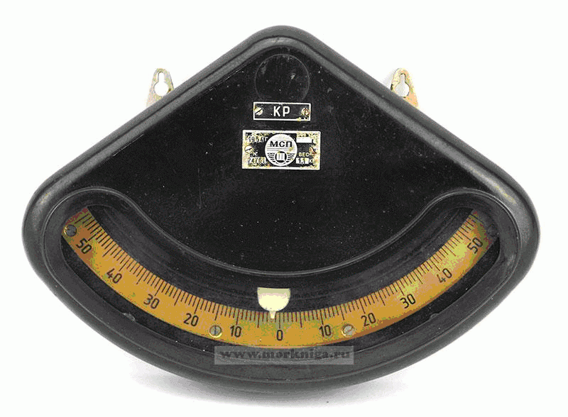
Mechanical inclinometer.
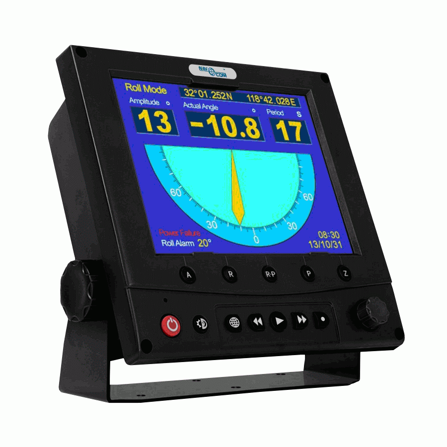
Electronic krenodifferentometer.
I, for obvious reasons, will be making a prototype of an electronic inclinometer.
To build an electronic inclinometer, in the general case, we need to know the roll and trim of the ship at the current time. It would be desirable, of course, to use conventional mechanical gyroscopes with an electronic device to write off the angle for this, but the cost of such a device will be very, very high. Meanwhile, the cost of the Delta 401 electronic inclinometer (its display unit in the picture above) with all the necessary certification was (I don’t know how much it is now) about 350 thousand rubles. This is too small for an inclinometer with mechanical gyroscopes. And the dimensions of the sensor for this inclinometer are very small. So what could be inside? The option to buy this device and see, alas, disappears – I will be very sorry for 350 thousand rubles. However, we can assume that at least micromechanical accelerometers and gyroscopes are installed inside the sensor. Like it or not, I can’t say, but I decided to try to build my own version of the inclinometer precisely on such things.
Of the widely available (both in price and availability) for an amateur on aliexpress, there is a GY-521 module on the well-known MPU6050 chip. This microcircuit is an assembly of three micromechanical gyroscopes and accelerometers with an additional thermal sensor.
The parameters of the MPU6050 chip are as follows:
– Accelerometer operating ranges: ±2g, ±4g, ±6g, ±8g, ±16g
-Operation ranges for gyroscope: ±250°/s, ±500°/s, ±1000°/s, ±2000°/s
This chip is connected via the I2C bus.
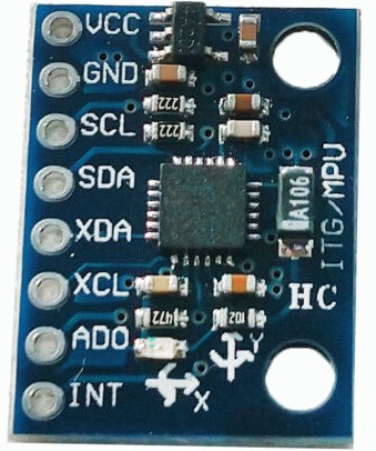
GY-521 module with MPU6050.
For the inclinometer, I chose the operating range of the accelerometer as ± 2g, and the gyroscope ± 250 ° / s. I think this will be quite enough for a relatively slowly rocking ship.
A micromechanical gyroscope has a noticeable drift and without an accelerometer it will not allow you to accurately measure the angle, therefore, in order to obtain roll and trim angles based on three accelerometers and gyroscopes, you will need to somehow combine the readings of accelerometers and gyroscopes. In other words, we need some kind of algorithm for generating angular information. Such algorithms naturally exist. For example, AB filter, Mahoney, Madgwick or Kalman filters. For my device, I took the Madgwick filter, good there is a ready-made example of a simple program here. I won’t say I understand exactly how this filter works, but luckily the filter program linked doesn’t require it. Before submitting the readings of the accelerometers to the filter, they should be calibrated (to find out the zero offset and scale factors), for example, using this method. Tests on a oscillating stand showed that after calibrating the accelerometers, the filter gives the correct roll and trim angles.
The result of the filter will be the two angles we need. Why two and not three? And the thing is that the third angle (yaw) cannot be obtained only from accelerometers and gyroscopes – the filter does not have a vector by which it could correct the course. For roll and trim, such a vector is given by the accelerometer, which shows the direction of gravity at times when there is no acceleration. But for yaw, accelerometers do not provide any information, therefore, without a heading sensor, the filter cannot give out yaw. You can take a magnetic compass as such a sensor, but it is not in the MPU6050 (but it is in other models of the MPU series). Since I don’t need yaw, I didn’t bother with a magnetic compass.
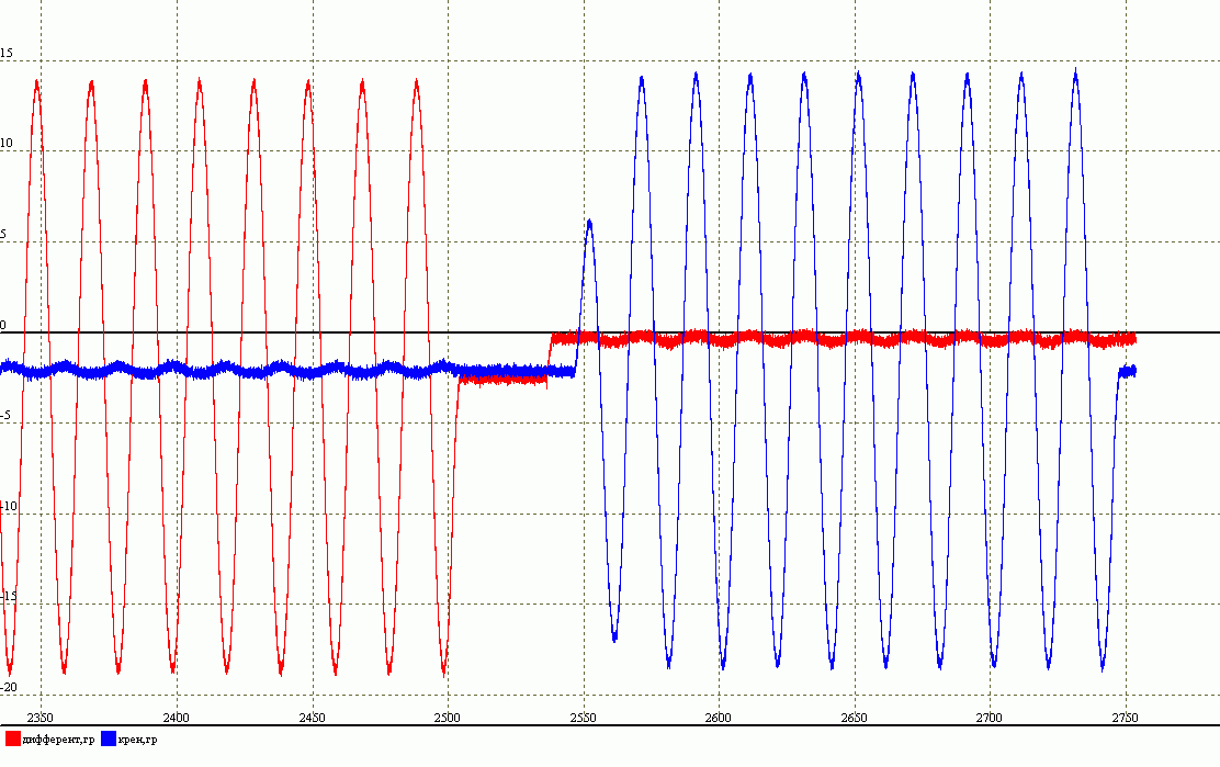
Angles just after the Madgwick filter.
Since the ship should not rock faster than 1 Hz, the resulting angles are sent to a digital low-pass filter with a cutoff frequency of 1 Hz. And now the angles after the LPF are used in determining the oscillation parameters according to the following algorithm.
Having two corners, we simply look for the upper highs and lower lows for each and the time they are found. At the same time, I believe that the ship will go through zero in the corners when rolling (but I can be wrong – for this case I also made an option taking into account fluctuations relative to the calculated current static value of the angle), which allows me, being in the lower half in the corner (the angle is negative), update the current minimum by resetting the current maximum (it is in the other half of the angle) to zero (as the minimum value of the maximum), and, being in the upper half (the angle is positive), update the maximum by resetting the current minimum to zero. It may sound confusing, but it’s actually very simple. Thus, the halves alternate, and at the moment of zero crossing (with some hysteresis of 0.5 degrees) the high/low reached update the stored values of highs and lows and the time when they were found. The half-sum of these memorized values gives the static angle, the half-difference gives the amplitude value, and the time intervals (for maxima, their own, for minima, respectively, their own) oscillation period. A situation may occur when the ship suddenly stops oscillating through zero. In this case, after 50 seconds, the readings of the period, amplitude and static angle are reset to zero.
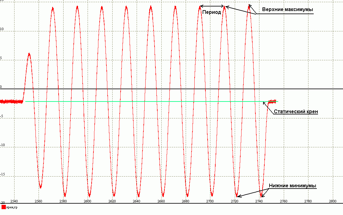
Determination of angle parameters.
To build a prototype of the inclinometer, I took the STM32F407 Discovery ward, connected the GY-521 module and a display with a resolution of 320×240 to it via I2C.
The display looks like this:

And it all works like this:
Video of the prototype inclinometer operation.
The source code of the program for the prototype of the inclinometer.
In general, my prototype turned out to be quite functional, although I did not conduct real tests on the ship due to the lack of a ship in my possession. It is also not clear whether the Madgwick filter will be able to correctly produce angles with the actual movement of the vessel (after all, accelerometers can introduce a constant offset all the time).
Unfortunately, I could only come up with such an algorithm for the operation of the crenodifferometer. To determine the oscillation parameters, I also tried to use the FFT, but the result was completely unsatisfactory. If anyone knows how else you can get the angles and oscillation parameters, I will be glad if you give me an idea.
