Fun lessons from WinCC OA. Modbus TCP driver
Within the framework of the “basic” course, the issues of working with drivers in WinCC OA are covered very mediocrely, and within the framework of my basic course – even more mediocre. In order to correct this shortcoming, today’s note was written.
It should be noted that for reasons that are not clear, setting up the Modbus TCP driver is more complicated than S7/S7plus. A simple poke method (the so-called “engineering intuition”) cannot solve the problem, you need to know some of the nuances. This is very well described, for example, by Vyacheslav Lapshin on his website “Quick Projects”. However, a number of details were omitted from his description, so I will create my own version of the guide.
I am working in CASCADE environment version 3.18 beta. In fact, this is an OEM supply of WinCC OA from SibCom (https://www.sybcom.ru)
As a server (slave device) of the Modbus protocol, I have a freely programmable PLC.
I traditionally work in an English-speaking environment without switching to Russian.
In case of ambiguities, I recommend referring to the “numbered” parts of the basic course.
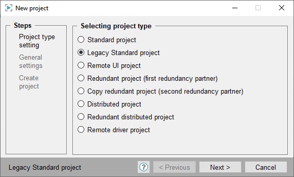
First of all, we create an empty project with “classic” security settings and selected NextGen archiving. I do not describe all the steps of creating a project, these are already obvious things. I do not set the root password for the educational project.

Run the created project and go to the console. We add the Modbus driver (namely, the modbus driver, not the modbus server!). When adding the “-num 10” option, set it to the number 10.


We make sure that the driver has started, and it has started, since its status in the console is 2, and the status color is green.

And now we are doing a very non-obvious thing. Open the config file of our project. I remind you that it can be opened through the project properties in the project manager.


And there we must enter the following:
[mod_10]
tcpServerPort = 502
Do not forget that the config file must end with an empty line.

The 10 in the mod_10 section obviously matches the driver number we specified when we added it to the console. After changing the config file, you must restart the modbus driver. Slava writes that the whole project needs to be restarted. However, I specifically conducted an experiment and did “this way and that way.” In my case and in my version it turned out to be sufficient to restart only the driver. The first time, of course, the Windows firewall kicked in and asked me to set the appropriate permissions.

In subsequent experiments, the firewall is already configured and does not ask for anything.
Next, go to System Management and look for the modbus driver settings.


Press the Create button and add Mod_Plc_10 to the list. As you might guess, 10 is the driver number.

Add the ip-address of our modbus TCP server, check the Active box. This is what the settings look like now. I remind you that the Unit Address in the full implementation of the Modbus TCP protocol is used only for TCP – RTU gates. Normal Modbus TCP servers ignore this parameter. But there are also reverse cases, and the server, not being a gate, still controls its Unit ID. Since everyone goes crazy in their own way in the implementation of the Modbus protocol, it is difficult to predict the behavior of the slave device in advance. In our case, the Modbus TCP server is implemented correctly, and the Unit ID is ignored.

Click the Apply button. If you expect that after clicking the state, instead of Not Connected, it will become Connecting or Connected, then you are hoping in vain. The connection state will change only after adding the first _address config to any data point, for which we traditionally open the para module. I use the predefined DPT ExampleDP_Int and create the first DP called MyInt.

Add the _address config and start configuring it


We will work with storage registers. The very first register in my PLC is a 16-bit signed Int that increments by 1 every second in the PLC program. Accordingly, we specify the conversion type = Int16. Don’t forget to add a poll group.

In the survey group, do not forget to activate the group, otherwise the exchange will not work.
Finally, we make the address active (check the box).

Go to config _original.

The value read once per second corresponds to the value in the PLC. This experience was a success. By the way, after adding the first signal, the message Connected appears in the driver window.

The next two registers in my case are a 32-bit Int. Let’s get another data point named MyDInt in the same type and set it up.

The conversion type is already Int32, these are two registers. We set the offset – 1 (zero register is MyInt, the first and second registers are MyDInt). The survey group remains the same. We pass to the original config and observe invalid data.

The value of the signal here is either several millions, or several billions, which is radically different from the value in the PLC = 5440 (every second increment is also programmed for this DInt). Let’s go to the driver settings. One Modbus register is 16 bits, two bytes. Two registers is 32 bits, 4 bytes, or double word. And the order of bytes in a word may not be known in advance. We look at the advanced settings tab and find the order of the registers. What is set by default – I do not know. But just in case, let’s try the Big endian order, like the Intel processors.


Don’t forget to click Apply. After this change, the value of MyDInt matches the value in the PLC. Of course, while I am writing this note, time is passing, and now the signal value is no longer 5440, but a little more.

Just in case, we look at MyInt, if something has broken there.

It didn’t break, which is to be expected. With the next parameter, let’s get a variable of type Real (also, two registers). On the controller side, this value is no longer forced, so let’s write both reading and writing. Creating and configuring a data point of type ExampleDP_Float

The value set on the PLC side was considered

Let’s add the _smooth config to this DP in the old/new comparison mode. Otherwise, it will be problematic to drive in a new value in the Para module, because it will be overwritten every second.

We change the value in the Para module and climb to check the controller. Everything is working.


And finally, I decided to check whether it is possible to set a DPE of type bool and read it as a bit of a storage register. As it turned out, you can.

The fifth register is the word MyWord in the PLC. I specify bit number = 1 (numbering in this case from one). I try to read/write the value, everything works out.


The sixth register in the PLC data block is represented by one bit. I draw your attention to the fact that in this particular case I must set the bit number not to 1, but to 9, since the bytes in the word are being reversed, and this cannot be won. This is primarily due to the alignment of information in the Simatic data blocks by word in the case of standard access.